ABS diagnostics using MAZ light codes
Entering diagnostic mode
To test the system using flashing light codes, you must:
- — turn on the remote "mass" switch button and turn the starter switch key to the "instruments" position;
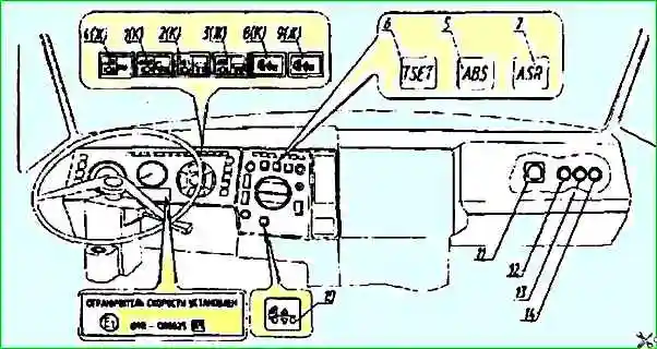
- — switch the control unit to diagnostic mode by pressing the diagnostic button 12, located under the right cover of the instrument panel (see Fig. 1), until the starting light signal appears on the control lamp
If the "ASR/INF" lamp lights up for 4 s (starting light signal) and then goes out, the unit has entered diagnostic mode.
Order for displaying information about configuration and malfunctions
After the starting light signal, there is a 2 s pause for 4 s.
Next, information about the current ABS configuration is displayed - the "ASR/INF" lamp lights up 2 times for 1.5 s with a 0.5 s pause.
After displaying the configuration code, there is a 2 s pause and then the fault codes are displayed.
The display of each fault code consists of two information blocks of light flashes (blinks): the 1st block and the 2nd block with a 1-second pause between them s.
If there are no faults, the lamp will not blink (code 0-0), if there are several, the codes will go sequentially with a pause of 2 s between codes.
During the output of the information block, the lamp blinks for 0.5 s, with a pause of 0.5 s.
Procedure for erasing information about faults
If the faults were eliminated during repair work, their codes must be erased from the unit's memory. This is done by pressing the diagnostic button again (see Fig. 2) before the moment of issuing the fault codes and holding the button while the codes are being issued.
2 s after the code of the last recorded fault is output and the button is released, the error codes will be erased.
Then the electronic unit will automatically exit the diagnostic mode, accompanied by a single flash lasting 0.5 s.
Notes. 1. After the ABS system exits the diagnostic mode, a repeated automatic test of the system faults is performed.
In this case, if the fault codes have been erased, but the faults themselves have not been eliminated, their codes will be re-written into the memory.
2. ABS configuration information cannot be erased or changed using the diagnostic button, this can only be done with a diagnostic tester.
Checking the braking efficiency
The initial braking speed during the braking efficiency check must be at least 40 km/h.
To display information about the braking efficiency, when entering the diagnostic mode, i.e. during the issuance of the starting light signal lasting 4 s, press the diagnostic button again until the second starting light signal lasting 2 s appears.
2 s after the second starting light signal, the light code for the effectiveness of the last braking will be displayed in the form of 3 blocks of flashing light codes that correspond to the decimal number of the average deceleration of the car (1st block, 2nd block, 3rd block, i.e. X.XX m/s²).
Each block is separated from the other by a pause of 1 s.
For example: ◙◙◙ ◙◙◙◙◙ is equal to 3.51 m/s².
After the information on braking efficiency is displayed, the diagnostic mode is automatically exited, accompanied by a single blink lasting 0.5 s and subsequent automatic testing of system faults.
Note: The ABS BPO "Ekran" also has a function for permanently storing information about pre-emergency operating modes (speeds and rotation times of the vehicle's wheels) over the last 40 seconds of movement.
This information is recorded in a special memory device, the so-called black box, and can only be read during computer diagnostics with a special diagnostic tester at a service station, which is connected to diagnostic connector 11 (see Fig. 2).
Light codes for malfunctions in the ABS BPO Ekran system

Note: 1. The letter designation of the wheels corresponds to the diagram
2. KZ – short circuit
For example:
◙ ◙ ◙ ◙ means the fault code is 3-1.
After the data on the last recorded fault is displayed or if there are none, the diagnostic mode is automatically exited, accompanied by a single flashing lasting 0.5 s.
After the ABS system exits the diagnostic mode, a repeated (automatic) test of the system faults is performed again.
")

")
")
")
")
")
")
")