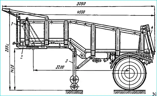
A single-axle frameless dump semi-trailer (Fig. 1) with rear unloading, with an open platform and an opening tailboard with a lifting capacity of 13.5 tons is designed for the transportation of various bulk construction materials on roads of categories I and II
The main traction vehicle for towing is the MAZ-504G truck tractor.
The axle, hubs, wheels and tires of the dump semi-trailer are the same as on the MAZ-5245 semi-trailer.
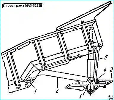
Traction frame with rolling plate
The semitrailer is coupled to the tractor via a kingpin pressed into the seat of the rolling plate 3 (Fig. 2).
The diameter of the coupling kingpin is 50.8 mm.
Traction force is transmitted via the traction frame 2, connected by axles 1 to the rolling plate 3. The axles are locked from movement by pins fixed to brackets.
The rolling plate is a welded structure, the basis of which is a metal sheet 6 mm thick.
A kingpin socket with a pressed kingpin is welded to the plate between the longitudinal channel beams and the crossbars.
The reliability of the kingpin fastening is additionally ensured by screwing a shank into it lower support of the cylinder (tail thread M42x x1.5), while the plane of the support is pressed against the kingpin socket.
Cast brackets 4 for fastening the rolling plate to the platform are welded along the kingpin axis on both sides of the plate.
Traction frame 2 is welded from two side members and three cross members made from channel 14a. At the ends of the side members, forged eyes are welded in for connection with the rolling plate and the platform.
Reinforcing strips are welded in inside the side members and along the end of the shelves, creating a box-shaped section.
The first cross member is used to attach the platform lifting limiting chain, and the chain release spring is attached to the second cross member.
Maintenance of the rolling plate and the traction frame consists of periodic inspection and tightening of the axle fixing pins, lubrication of the axles in accordance with the lubrication chart.
Repair
If the radial wear of the kingpin is more than 2 mm, it must be replaced. The kingpin must be removed after disconnecting the hydraulic cylinder from the lower support, for which:
- - install the semitrailer on the support devices, unhook the tractor, disconnect the hoses, brake the semitrailer with the parking brake and install trestles under the drawbar frame;
- - disconnect the locking rod 1 (see Fig. 3) and remove it from the platform brackets and the drawbar frame. The drawbar frame with the rolling plate will lower onto the trestles;
- - disconnect the hydraulic lift from the lower support of the cylinder and move it to the side, bend the stopper from the lower support and unscrew it from the kingpin, knock the kingpin out of the socket.
The kingpin is installed in the reverse order.
If axle 1 (see Fig. 2) of the drawbar frame mount is worn out, it must be replaced. Axle made of steel 40-45 Ø 50-0.17, length 132 mm.
At a distance of 15 mm from the end face, perpendicular to the axis of the part, drill a hole Ø 19 mm for installing the locking pin.
In the bracket for fastening the drawbar frame, the hole for the axle is made Ø 50+0.50 mm, in the eyes of the drawbar frame, the hole for the axle is made Ø 50+0.25 mm.
The axles on bracket 4 can be replaced, for which the unloaded platform is raised by 20-25 °, stop 5 is removed and its end with a pin is inserted between the reinforcing ribs of the first crossbar of the platform, and the opposite end with a guide pipe is inserted into the socket of the right bracket of the rolling plate. Then lower the platform to the stop.
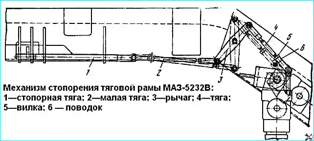
Traction frame locking mechanism
Device. To prevent the traction frame with the rolling plate from lowering to the ground when uncoupling the tractor from the semi-trailer, a traction frame locking mechanism is used (Fig. 3).
Before uncoupling the tractor from the semi-trailer, it is necessary to lower the support device, which will turn at a certain angle relative to the axis.
A leash is attached to the body of the support device, connected by rod 4 to lever 3 of the locking mechanism.
The lever moves the locking rod 1 with the help of the rod 2. The locking rod enters the holes of the ears of the drawbar frame and the platform base and thus eliminates the possibility of the drawbar frame with the rolling plate falling.
In the working position of the semitrailer, the support devices must be raised.
Maintenance of the locking mechanism consists of timely cleaning of the connection of the rods and forks from dirt. It is also necessary to ensure that the rods of the locking mechanism are not bent.
If the rods are bent, they must be straightened. If the locking rod does not fully enter the bracket ears, it is necessary to adjust by rotating the rods in the fastening forks.
Possible faults of the drawbar frame and the rolling plate and how to eliminate them
Cause of fault - how to eliminate
- The original position of the drawbar frame fastening axes is disturbed
Worn or lost pins for fixing the axes - Replace the pins
- Noticeable jerks when changing the speed of movement
Worn kingpin more than 2 mm - Replace the kingpin
Worn drawbar frame fastening axes - Replace the axes
Worn in the brackets or lugs of the drawbar frame fastening - Press repair ones into the brackets or lugs bushings
Suspension
The axle is suspended to the semi-trailer frame using longitudinal semi-elliptical springs - main and additional.
The main spring is divided into two groups:
- - the first group of springs with a deflection of 65-8 mm, the second with a deflection of 65+8 mm.
The additional spring is also divided into two groups:
- - the first group of springs with a deflection of 48+7 mm;
- - the second with a deflection of 48+1 mm.
Brake system
The brake system of the semi-trailer is similar to the brake system of the semi-trailer MAZ-5245. The parking brake operates in a manner similar to that of the MAZ-5206 trailer.
A special feature of a frameless dump semi-trailer is that during unloading it is necessary to ensure that the semi-trailer rolls up to the tractor or the tractor rolls up to the semi-trailer.
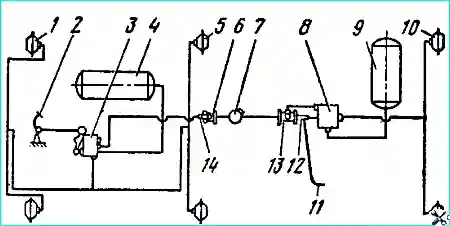
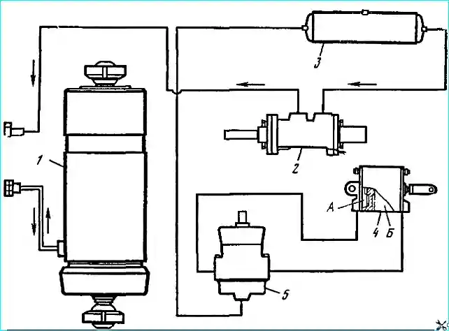
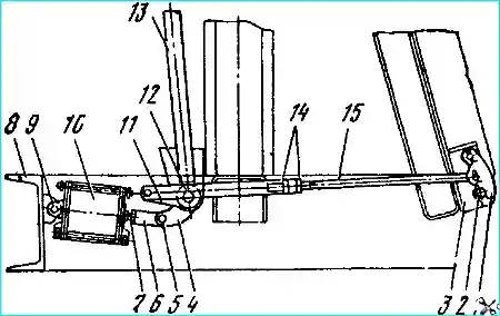
Taking this into account, the pneumatic brake drive system of the road train consisting of the MAZ-504G tractor and the MAZ-5232V semi-trailer provides the ability to brake one tractor or one semi-trailer depending on the unloading conditions (Fig. 4).
Depending on the unloading conditions, braking should be carried out as follows.
When unloading into a dump or bunker, it is necessary to brake the semi-trailer, for which the handle 14 of the release valve 6, installed on the tractor, should be moved to a position perpendicular to the longitudinal axis crane.
In this case, air from the connecting line of the semitrailer is released into the atmosphere, as a result of which the air distribution valve 8 is activated and the semitrailer is braked without pressing the brake pedal 2 in the tractor cabin.
After unloading is complete, the handle 14 should be returned to its original position.
In the case of unloading the semitrailer on the platform, in order to better remove the load from the platform, it is advisable to brake the tractor, thereby ensuring the rolling of the semitrailer.
To do this, the handle 12 of the manual brake control valve of the semitrailer installed on the semitrailer must be moved to a position perpendicular to the longitudinal axis of the crane using the rod 11, as a result of which the air distribution valve 8 will be activated and the semitrailer will be released.
The tractor is then braked by pressing the brake pedal in the tractor cabin.
After unloading, handle 12 should be returned to its original position.
In other cases, provided that safety regulations are met, it is permissible to unload the semitrailer with the tractor and semitrailer unbraked. In this case, both the semitrailer and the tractor can be rolled up.
It is not permissible to unload the semitrailer with both the tractor and semitrailer simultaneously braked, both with the service and parking brakes, since this will sharply increase the loads on the tipping and other mechanisms of the road train due to the impossibility of rolling the tractor and semitrailer, which can lead to their breakdown.
Electrical equipment
The electrical equipment consists of seven-pin socket, two rear lights that function as stop signals, parking lights, direction indicators, a license plate light, and reflectors mounted on the sides of the platform.
The platform of the dump semi-trailer is load-bearing, metal, with an automatically opening and closing rear side.
Internal dimensions of the platform: length 4420 mm, width 2290 mm, height in the front part 660 mm, in the rear 570 mm; the volume of the platform is 7 m³.
The platform consists of the body itself, a visor, a rear side, a mechanism with a drive for locking the rear side and rubber-metal shock absorbers.
The body of the semi-trailer is welded from stamped sections. The basis is made of side members made of 20a channel.
The sides are made of 3 mm thick sheet and reinforced with omega-shaped buttresses that turn into floor fastening crossbars.
The floor is two-tiered.
The first tier is a stamped corrugated profile 30 mm high and 2 mm thick welded to the side members, crossbars and the lower part of the sides.
The second tier is a 6 mm thick sheet welded to the lower floor and sides.
A stamped reinforcement with holes for installing add-on sides is welded along the upper edge of the sides.
A niche for installing a platform hydraulic lift is welded into the front side.
To protect the tractor from cargo falling on it, the front part of the body is attached with M10 bolts visor.
Four shock absorbers are installed at the front bottom of the side members to support the traction frame.
The tailgate opens around the upper axles in the side side brackets.
The side opens and closes automatically depending on the platform lift angle.
If necessary, you can use the manual lock drive located on the left side near the tailgate.
The spring mounting brackets are riveted to the platform side members, the support device brackets and the traction frame brackets are welded.
The mudguard mounting brackets are welded to the two rear side buttresses. The mudguards are attached to the brackets with M8X20 bolts.
The platform maintenance consists of periodic washing and touching up.
The tailgate lock is adjusted if necessary. Adjustment of the manual lock of the tailboard is carried out if there is a gap in the plane of the side contact of more than 6 mm.
Repair of the platform is usually carried out by welding if the floor or sides are damaged by cargo.
Damaged areas are straightened and, if necessary, welded with the additional installation of reinforcing plates. The reinforcement plates are welded with continuous seams.
Platform lifting mechanism
The dump semi-trailer operates in conjunction with the MAZ-504G tractor unit, which is equipped with special hydraulic equipment designed to lift the platform of the transported dump semi-trailer and driven by the engine (Fig. 5).
The platform lifting mechanism provides for lifting the platform to an angle of 45°, lowering it, stopping in any intermediate position, automatic limitation of the lifting angle, shaking the platform at the end of the lift for better unloading of the cargo.
In addition, automatic opening and closing of the platform tailboard is provided.
The platform lifting mechanism is controlled remotely, pneumatically, from the driver's cabin using an air distribution valve.
Pneumatic Remote control of the platform lifting mechanism and tailboard locks makes the driver's job easier and reduces unloading time.
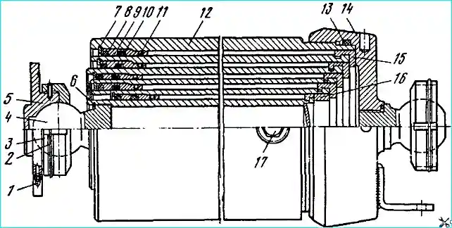
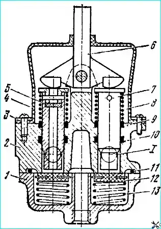
The hydraulic cylinder is used to lift the platform. It consists of a fixed body tube 12 (Fig. 6) and five telescopically placed retractable links in it.
The sealing of the retractable links is achieved by rubber rings 10 of circular cross-section placed in the channel in the guide sleeves 9.
The guide sleeves themselves are sealed in the pipes with the same rings 11. The sealing rings of the movable links are protected from dirt and dust from the outside by dirt-removing rubber rings 8.
The direction of the retractable links and the limitation of their travel is achieved by means of the upper guide sleeves, secured with locking rings, and the guide half rings 15, laid in the movable links located in the lower part.
From below, the cylinder body is closed by a bottom 14, sealed by a rubber ring 13.
The upper support of the cylinder (in the platform) is made in the form of a ball joint.
The ball pin 4 is secured in the internal retractable pipe with the help of a locking ring 6 and simultaneously to the spherical heel 5 of the platform with a nut 3, locked locking ring 2.
A similar hinged connection connects the lower end of the cylinder to the rolling plate.
The hinged fastening of the cylinder to the rolling plate and the platform frees all the cylinder links from the effects of transverse loads that occur when the platform is tilted.
Oil is supplied to the cylinder through an opening in the lower part of the fixed pipe, closed with plug 17.
The ball joints of the upper and lower cylinder supports are lubricated through oilers 1.
The platform lifting limiting mechanism (Fig. 7) is designed to limit the angle of the platform lift and ensure its shaking at the end of the lift.
The platform lift limiting valve 12 is installed in the crossbar opening and secured with bolt 14.
By means of rod 4 connected to pivotally secured lever 6, as the platform lifts, tip 7 moves to the right by a gap of 3.0-3.5 mm between nut 11 and the end of the platform lift limiting valve cover (Fig. 8).
When the platform lifts to the set angle, lever 6 (Fig. 7) acts on tip 7, which moves rod 9 (see Fig. 8) of the valve. In this case, the rod rests against valve 5 and tears it off the seat.
Air under pressure from cavity "A" rushes into cavity "B" and then enters the pneumatic chamber of the control valve installed on the tractor.
In this case, the pressure line of the platform lifting mechanism connects to the drain line, and the platform, displacing oil from the cylinder, goes down at a certain angle until valve 5, under the action of spring 4, is pressed against the seat, and rod 9 returns to its original position by the force of spring 6.
Air from the pneumatic chamber of the control valve is released into the atmosphere through the hole "B" in the valve stem 9, after which the platform begins to rise and the cycle is repeated.
Alternate opening and closing of the valve provides shaking of the platform at the end of the rise, which greatly facilitates the dumping of the cargo.
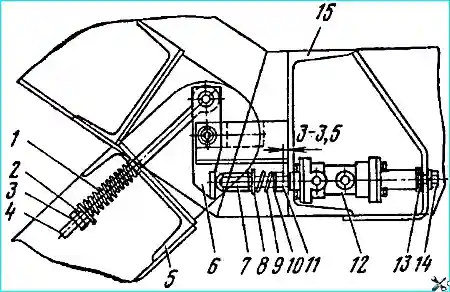
The rear side locking mechanism (Fig. 9) is designed to automatically open the side at the moment of lifting the platform and lock it in the transport position.
The mechanism drive is pneumatic with an automatic valve for controlling the side locking mechanism, which directs air to the side locking pneumatic cylinder.
The side trunnions 2 are held by two grips 1, located on both sides of the platform. The grips 1 are connected by rods 15 to levers 11, rigidly fixed on a common shaft 12.
Each of the rods consists of two components, connected to each other by a thread in such a way that the total length of the rod can be changed.
When the shaft 12 is turned at a certain angle in one direction or another, the grips 1 clamp or release the trunnions 2 of the tailboard.
A double-acting swinging pneumatic cylinder 10 serves to drive the shaft 12.
The covers and the cylinder body are pulled together by four studs.
The piston and rod are sealed with rubber sealing rings.
The cylinder is hingedly secured by pin 9 to the crossbar 8 of the platform, and its rod is connected by means of a fork 6 through pin 5 to lever 4, rigidly fixed on the shaft 12 in its middle part.
Air is supplied to the pneumatic cylinder through openings in the covers via air ducts connected to the automatic valve for controlling the side locking mechanism.
When air is supplied to cavity "A" (Fig. 5) of the cylinder, the piston will move to the right, turning shaft 12 by means of lever 4 (see Fig. 9). Rods 15 will also move, turning grips 1 counterclockwise, and the side trunnions will be released.
When air is supplied to cavity "B" (see Fig. 5) (in this case, cavity "A" will be connected to the atmosphere through the valve), all the links of the mechanism will move in the opposite direction and the grips, turning clockwise, will clamp the side trunnions.
When the semitrailer is moving, cavity "B" of the cylinder is under air pressure and thus the piston is forcibly held in the position corresponding to the closed side.
Even in the absence of air pressure, spontaneous opening of the side is excluded, since the rods 15 (see Fig. 10) when the mechanism links are in the position corresponding to the closed side are located above the axis of the shaft 12 (they pass the dead point), which prevents this shaft from turning clockwise.
To be able to control the side grips in the event of any malfunction of the pneumatic drive, a handle 13 is installed on the shaft 12 on the left side of the semitrailer, with which the driver can open or close the side.
When the side is closed, the end of the handle rests against the rear buttress of the side side, which allows the pneumatic cylinder to be relieved of the loads that appear when the load presses on the rear side.
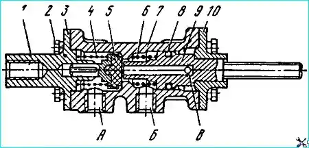
Automatic control of the side locking mechanism is performed using valve 5 (see Fig. 5).
Air from the semitrailer air cylinder is supplied to the valve through the hole in the lower cover 1 (Fig. 10) of the valve.
When the platform is raised, the hook of the drawbar frame acts on the lever 6 of the valve mounted on the platform crossbar, which, rotating around the axis, presses on the pusher.
When descending, the pusher presses the rubber valve 12 from the socket.
Air rushes from the lower cavity into the space between the pusher and the drilling in the housing and through the hole 1 in the housing through the pipeline is supplied to the side locking pneumatic cylinder.
When the platform is lowered, the hook of the drawbar frame acts on the lever 6, which, rotating around the axis, presses on the other pusher.
The process occurs similarly to that described, but the air is supplied to another cavity cylinder.
The air expelled from the cylinder is released into the atmosphere through the hole in the pusher.
The platform safety stop is located on the right side of the semitrailer.
To install the stop, raise the platform to an angle of 20 - 25˚, then remove the stop and insert the end with the pin into the platform crossbar between the ribs.
The guide tube should be lowered into the socket of the roll plate bracket, then lower the platform to the stop.
It is prohibited to use the stop when the platform is loaded.
Maintenance. During operation, it is necessary to systematically check the fastening of the hydraulic cylinder to the frame and to the platform, monitor the tightness of its seals and regularly lubricate the ball joints of its upper and lower supports through grease nipples.
It is recommended to check the cylinder fastening during TO -1. In this case, it is necessary to check the reliability of the locking of the nuts of the upper and lower cylinder supports.
After long-term operation, minor oil leaks may appear on the surfaces of the hydraulic cylinder extension links, which are a consequence of the scraping of the oil film by the sealing rings.
They should be removed with a clean, dry cloth. Heavy oil leaks indicate wear of the sealing rings.
In this case, the sealing rings must be replaced, since the presence of oil on the working surfaces of the cylinder links leads to contamination and, consequently, to accelerated wear of the parts.
Under normal operating conditions, the service life of the sealing rings corresponds to 80-100 thousand km of the semi-trailer's mileage, however, with significant overload of the semi-trailer and when using the service life of the rings is sharply reduced when contaminated with oil.
The need for frequent replacement of the sealing rings of the hydraulic cylinder extension links under normal operating conditions indicates wear and the need to replace the upper guide sleeves.
To avoid breakage of the lower guide half rings of the cylinder links, it is necessary to avoid lowering an unloaded or even partially unloaded platform, since during accelerated lowering of the platform, the guide half rings are subjected to sharp impact loads.
For normal operation of the hydraulic cylinder, a correctly set limitation of the maximum platform lift angle is of great importance, which is achieved by adjusting the platform lift angle limitation mechanism.
A correctly adjusted mechanism should not allow the platform to be lifted more than 45°.
With such an angle of platform lift, the cylinder stroke is slightly less than the maximum possible and the cylinder therefore does not work in tension.
Maintenance of the tailboard locking mechanism is reduced to to systematic monitoring of the tightness of connections, pipelines and hoses supplying air to the cylinder, the tightness of the cylinder itself and to periodic checking of the adjustment of the mechanism.
Significant air leaks through the connections of the air pipes, seals of the covers of the pneumatic cylinder and its rod are usually determined by ear.
Minor air leaks can be detected using a soap solution. The tightness of the system should be checked during TO-1.
It is recommended to adjust the mechanism only if necessary, when a malfunction in its operation is noticed.
Adjustment of the tailgate locking mechanism consists of correctly selecting the length of the rods 15 (see Fig. 9) and the length of the pneumatic cylinder rod 10.
The length of the rod 15 is changed by moving the nuts 14 along the thread of the rod. The length of the rod is changed by unscrewing or screwing the fork 6 onto the cylinder rod.
It is recommended to adjust the side locking mechanism in the following order:
- - release air from the tractor pneumatic system, unpin and remove pin 5 securing the cylinder rod to lever 4 and push the cylinder rod until the piston stops in the lower cover;
- - pressing the handle with the free end to the buttress, bring the length of the left rod 15 by turning nuts 14 to a value that ensures a reliable clamping of the side journal between bracket 3 and grip 1.
Also adjust the length of the right grip rod;
- check the operation of the side locking mechanism manually. To do this, open and close the locks 2-3 times with handle 13.
If the force required to move the rod through the dead point is too great, the length of the rods should be increased. Tighten nuts 14;
- - extend the cylinder rod by 5 mm, loosen nut 7 and rotate the fork in the required direction to align the fork holes with the hole in lever 4, while tightly pressing it to the bracket at the end of the handle;
- - insert and cotter pin finger 5. Lock nut 7;
- - start the engine, bring the pressure in the pneumatic system to 4 kgf/cm² and raise and lower the empty platform several times, checking the operation of the side locking mechanism.
A correctly adjusted locking mechanism should ensure reliable clamping of the trunnions by the grips, the absence of spontaneous opening of the side and the grips touching the side trunnions when it is opened and closed during the process of raising and lowering the platform.
Opening and the tailboard should close at a platform lift angle of 10–15˚.
If this occurs at a greater or lesser platform lift angle, it is necessary to move the automatic valve for controlling the tailboard locking mechanism in the bracket slots until, at a platform lift angle of 10–15°, the valve lever 6 (see Fig. 7) is able to come into contact with the hook on the drawbar crossbar, thereby opening air access to the pneumatic cylinder of the tailboard locking mechanism.
Adjusting the platform lift limiting mechanism. When the platform lifting mechanism is adjusted correctly, the platform lifting limit valve should operate at a platform lifting angle of 45°.
The last retractable pipe of the cylinder should extend by 250-300 mm and the platform should shake automatically.
If, when the platform is fully raised, the last pipe extends more than 300 or less than 250 mm; it is necessary to carry out the adjustment in the following sequence:
- - raise the platform with the lifting mechanism and install the safety stop;
- - make sure that the distance from the end of the valve cover to the end of the nut 11 (see Fig. 7) is 3-3.5 mm and, if necessary, adjust the value of this dimension with nut 11 and tighten the lock nut 10;
- - change the working length of the rod 4 with nuts 2 and 3 to achieve a position such that the valve is triggered when the last pipe of the cylinder is extended by 250-300 mm. When increasing the working length of the rod 4 (when unscrewing and nuts) the platform lift angle increases, and when the length of the rod decreases, it decreases. After completing the adjustment, tighten the lock nut 3.
Repair
To remove the hydraulic cylinder, do the following:
- - lift the platform using a lifting mechanism or an external lifting device, securely lock it with a safety stop and drain the oil from the system;
- - remove the locking ring of the upper cylinder support nut, unscrew the nut, disconnect the discharge line hose from the cylinder, remove the locking ring of the lower cylinder support nut and unscrew the nut;
- - remove the cylinder from the semitrailer.
The sequence of disassembling the hydraulic cylinder is as follows:
- - unscrew the bottom of the cylinder body, remove the sealing ring from the bottom, push each retractable link out of the body in sequence from the link of the smallest diameter to the largest. Remove the guide half rings from each extracted link;
- - remove the retaining rings for the upper guide sleeves from the cylinder body, as well as from the first, second, third and fourth retractable links, and then the guide sleeves themselves;
- - remove the outer and inner sealing rings and wiper rings from the grooves of the guide sleeves.
Wash and carefully inspect all cylinder parts. Replace worn parts. The most worn parts of the hydraulic cylinder are the sealing rings of the moving links and the wiper rings.
If the tightness of the cylinder sealing rings was insufficient before disassembly, the rings should be replaced.
Carefully inspect the guide half rings.
If there are chips or cracks on them, which could have appeared as a result of lowering the loaded platform, the half rings must be replaced.
After long-term operation of the hydraulic cylinder (approximately after 80 - 100 thousand platform lifts), it may be necessary to replace the upper guide sleeves, which is usually indicated by increased gaps between the guide and the corresponding link, which cause accelerated wear of the sealing rings.
The hydraulic cylinder is assembled in the reverse order of disassembly.
In this case, it is necessary:
- - thoroughly wash all parts of the hydraulic cylinder, blow with compressed air, lubricate the sealing rings and the inner surface of the guide sleeves with solid oil before assembly;
- - assemble the hydraulic cylinder carefully, trying not to damage the sealing rings.
After assembly, the cylinder must be checked for smooth running and tightness. To do this, supply oil to the cylinder until it is fully extended, and then bring the pressure to 50 kgf/cm².
A properly assembled cylinder should extend smoothly under the action of the oil pumped into it, without markets, and upon reaching full stroke should withstand an oil pressure of 150 kgf/cm² for 5 minutes without leaks.
Install the cylinder on the semi-trailer in the reverse order of removal.
After installing the cylinder, carefully lock the nuts of the upper and lower supports with a locking ring.
Possible malfunctions of the hydraulic cylinder and how to eliminate them
Cause of malfunction - Method of elimination
- The cylinder links are extended in violation of the sequence, the links are extended jerkily, the platform does not lower completely
Jamming cylinder extension links - Disassemble the cylinder, eliminate the causes of jamming
- Abundant oil leakage through the extension link seals
Damage or wear of the sealing rings of the links or guide sleeves - Replace the sealing rings
- Oil leakage along the threads of the cylinder bottom
Damage to the sealing ring of the cylinder bottom - Replace the sealing ring
")

")
")
")
")
")
")
")