Compressor capacity at 2000 rpm of the engine crankshaft is 201 l/min
The compressor must be disassembled if noise and knocking occur during operation, as well as if the compressor significantly releases oil into the discharge pipeline
To remove the compressor from the engine, remove the drive belt, disconnect the pipelines and unscrew the compressor mounting bolts.
Disassemble the compressor in the following order:
- — unscrew the discharge valve plugs, remove the springs and valves. Use a square wrench with a head size of 10 x 10 mm to unscrew the valve seats;
- — remove the compressor pulley with a puller. Knock out the segment key;
- — unscrew the compressor head mounting stud nuts and carefully, having previously separated the head gasket, remove the compressor head;
- — remove the springs and inlet valves from the socket in the cylinder block;
- — unscrew the bolts and remove the air supply pipe;
- — remove the connecting rod caps and remove the pistons with connecting rods and assembly from the block;
- — remove the piston rings, take out the plugs and piston pin and separate the connecting rod and piston;
- — unscrew the bolts and remove the front and rear crankcase covers;
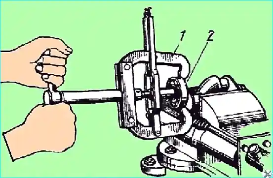
- — remove the rear cover seal with the spring, unscrew the thrust nut of the rear crankshaft bearing (Fig. 2) and remove the lock washer;
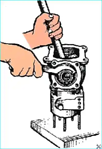
- — knock out the crankshaft assembly with the front bearing through the front bearing seat in the block. Press the front bearing off the crankshaft (Fig. 3);
- — remove the rear bearing retaining ring and press the rear bearing out of the block;
- — remove the oil seal from the front cover seat;
- — separate the block and crankcase, unscrew the stud nuts, carefully separating the gasket.
wash and carefully inspect the parts of the disassembled compressor. Blow out all channels with compressed air.
Checking the technical condition of compressor parts
During operation, the following compressor defects may appear:
- — in the cylinder head — cracks and chips, stripped threads in the tapered holes for fittings and elbows of pipelines, warping of the mating plane to the block;
- — in the cylinder block — cracks, breaks or scoring and wear of the cylinder surface;
- — in the compressor crankcase — wear of bearing seats, stripped threads for bolts and studs of covers and block, chips and cracks;
- — in the crankshaft — wear of connecting rod journals, rear cover seal and front cover oil seal;
- — wear of discharge and intake valves and their seats, unloading device parts, shrinkage or breakage of valve springs;
- — in compressor pistons — scoring, wear of the skirt, holes for pins and breakage of piston rings;
- — in the compressor connecting rod — wear of the upper head bushing and wear of the lower head liners.
Torn or worn threads in the block head and other compressor parts are eliminated by installing inserts with subsequent processing to the nominal size.
Worn seats and valves are replaced. After installing a new seat or valve, they must be ground in.
Splines ьки and nuts that have stripped threads or do not provide connections are subject to replacement.
The cylinder block and other compressor parts that have chips and cracks should be replaced with new ones.
Cylinders are repaired by boring them with subsequent honing to the repair dimensions given in Table 1.
When boring cylinders, the ovality and taper should not exceed 0.03 mm, and the perpendicularity of the cylinder surface relative to the plane of the joint with the crankcase should not exceed 0.03 mm over a length of 100 mm.
Worn pistons and piston rings are subject to replacement with repair kits specified in Table. 2.
The difference in piston weight should not exceed 15 g. The crankshaft main journals, if worn to a diameter of less than 34.99 mm, are welded and machined to a diameter of 35 mm.
Worn connecting rod journals are ground to the repair size and sets of connecting rod bearings corresponding to the repair sizes are selected for them.
When replacing the compressor piston group, pistons, connecting rods and pins should be selected by groups (see table).
Parts of the groups are color-coded. The piston and piston pin should be selected from the same group. When selecting a connecting rod, it is permissible to install a pin from an adjacent group.
Connecting rods that are bent are straightened. The non-parallelism of the connecting rod head holes is allowed to be no more than 0.1 mm over a length of 100 mm.
The front cover seal, which does not provide tightness, and the worn parts of the rear seal are not repaired and are subject to replacement.
Assembling the compressor
The compressor must be assembled in compliance with technical requirements in the following order:
- — assemble the piston with the connecting rod. When installing the piston pin into the connecting rod, it should fit tightly into the connecting rod hole under the force of the thumb.
Select the piston and connecting rod at an ambient temperature of 10 - 30˚ C without using grease, and during final assembly of the piston-pin, connecting rod-pin joint, lubricate with engine oil;
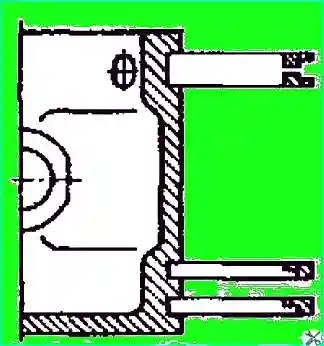
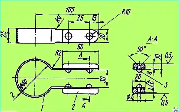
- — install piston rings on piston (Fig. 4). Install compression rings with groove on inner diameter facing up.
Install compression ring joints in vertical plane of piston pin axis on diametrically opposite sides of piston;
- — press rear crankshaft ball bearing into compressor housing until it stops against retaining ring. Press front bearing onto crankshaft until it stops.
Install crankshaft in housing, put on rear bearing lock washer, tighten nut until inner bearing ring stops against crankshaft and lock it;
- — install front crankcase cover, having pressed seal into it beforehand. Before installing the cover, lubricate the crankshaft journal with engine oil;
- — install the spring and seal in the crankshaft seat. When installing the spring, insert its ends into the crankshaft and seal bore.
Install the rear crankcase cover. Check through the hole in the cover that the seal can move freely in the seat. Turn the crankshaft; the turning force should not exceed 3 Nm;
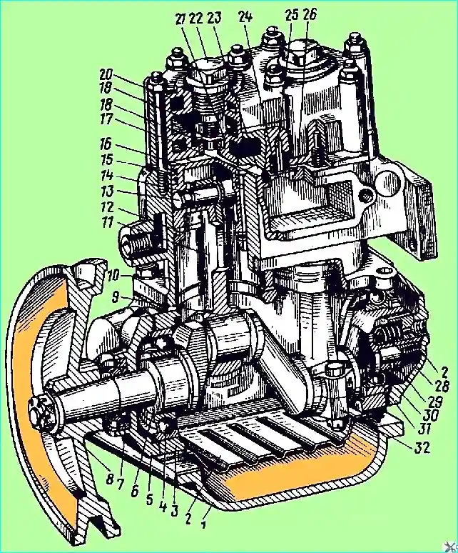
- — press into the block the seats 17 (see Fig. 1) and guides 26 of the intake valves; install the intake valves 25;
- — lubricate the plungers with engine oil and install them in the seats together with the rubber rings. The plungers in the sockets must move freely under a force of 5 N. Install the piston rods with the sockets in the assembly, the spring and the rocker arm of the unloading device;
- — install the gasket and assemble the crankcase with the cylinder block;
- — lubricate the cylinder bore, crankshaft journals, piston rings and main bearings with engine oil;
- — install pistons with connecting rods and compression rings in cylinders using a crimping tool (Fig. 5);
after installing connecting rod bearings, assemble the lower heads of the connecting rods. Tightening torque of connecting rod bolts is 12.25 - 13.7 Nm.
Align the hole for the cotter pin in the nut and in the connecting rod bolt, tightening the nut. Do not loosen the nut to install the cotter pin;
- — check the ease of rotation of the crankshaft; the torque for turning the crankshaft should not exceed 3 Nm;
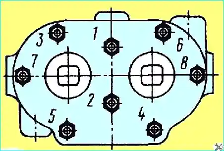
- — install the gasket and cylinder head. Tighten the head stud nuts evenly in two stages to a tightening torque of 12–17 Nm (Fig. 6);
- — screw the 18 (see Fig. 1) discharge valve seats into the cylinder head sockets, install the 21 discharge valves, 19 discharge valve springs and screw the 22 discharge valve plugs into the head;
- — install the key and press on the drive pulley. Secure the pulley with a nut and cotter pin;
- — test the compressor.
Testing the compressor
The test is performed on a special stand at 1200-1350 rpm of the crankshaft and oil pressure in the lubrication system of 118-245 kPa. The oil temperature should be at least 50 °C.
When the compressor is idling for 4-5 minutes, check by touch and by ear:
- — heating of the bearings;
- — noise of the bearings;
- — knocking of the pistons (there should be no knocking);
- — knocking of the fingers (there should be no knocking);
- — oil leakage (there should be no leakage).
After testing, install the compressor on the engine and adjust the relative position of the fan and compressor pulley grooves; adjust with shims.
Adjust the tension of the compressor drive belt.
Since 1999, a compressor with a capacity of 270 l/min at 2000 rpm of the crankshaft is also installed, differing in the device valve system.
Distinctive feature of the compressor
- — absence of discharge valve plugs and presence of a cover in the cylinder head.
Disassembly, technical condition check, assembly and testing are similar to the compressor with a capacity of 201 l/min, with the exception of a slightly different order of removal and installation of the valve system block head.
Table 1

Table 2

")

")
")
")
")
")
")
")