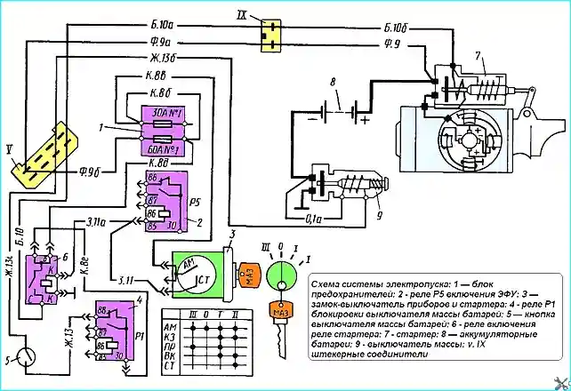
The electric starting system includes batteries, a starter, a battery battery disconnect switch, a switch-key for instruments and a starter, an electric torch device (ETD), a vapor-liquid heater (VSH), and intermediate relays
The electrical equipment of all these units and assemblies operates in the circuit shown in Fig. 1.

All the diagrams in this section have letters indicating the colors of the wires: B - white, G - blue; Zh - yellow; O - orange; R - pink; S - gray; Z - green; K - red; Kch - brown; Ch - black; F - purple.
To facilitate troubleshooting, the circuits in the diagrams also have a digital indicator, which is also indicated on the wires.

The starter is a DC electric motor with series excitation with a gear drive mechanism mounted in a single unit with it.
The mechanism is controlled by a traction relay installed on the starter housing.
Technical characteristics of the starter:
- - Type - ST 103A-01
- - Nominal voltage, V - 24
- - Nominal power, kW - 11
- - No-load current, A - 110
- - at a braking torque of 6 kgfm, A - 825
- - Voltage of switching on the traction relay. B - 20
- - brush spring pressure, kgf - 1.5
- - starter weight, kg – 34
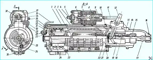
The starter design is shown in Fig. 2.
Gear 15 of the drive is engaged with the flywheel ring gear by means of traction relay 7.
The gear disengages automatically after the engine starts.
The starter is made according to a single-wire circuit, where the second wire is the vehicle ground.
To ensure a reliable connection to ground, there is a bolt 28 for connecting the flexible ground wire on the rear cover 31 of the starter.
There are windows in the cover for access to the electric brushes and inspection of the collector. The windows are covered with protective tape 1 from the outside.
For lubricating the bearings, channels with felt pads placed in them are made on the covers and in the starter housing.
The channels are closed with threaded plugs 10, 16 and 27. The starter is installed on the engine cylinder block bed and secured with two clamping clamps.
A pin is pressed into the engine cylinder block bed, ensuring the correct installation of the starter and preventing it from turning.
When the key of the instrument and starter switch is turned to position II (see Fig. 1), the contacts of terminals "AM" and "CT" of the lock are closed and voltage is supplied to intermediate relay 6 of the starter.
The relay closes the contacts of terminals B and C and voltage is supplied to the starter traction relay via wire B10.
Retractor winding the relay moves the anchor and through the lever 12 (see Fig. 2) feeds the pinion to the flywheel ring. At the same time, the contacts of the traction relay are closed and the starter motor is switched on. The engine is cranked.
During the start-up process, the pull-in winding of the traction winding is short-circuited (shunted) by the disk 6 of the relay anchor, and the pinion is held in the working position only by the field created by the holding winding, which consumes insignificant current.
After the engine is started, the pinion is automatically disconnected from the flywheel ring, screwing along the oblique splines of the anchor shaft.
The key of the switch-key returns to the working position I due to the springs of the lock, since the position of the key II is not fixed.
The traction relay disconnects the main working current, and the starter switches off.
At each TO-2, check the tightness of the connection of the wires to the terminals of the starter and batteries and clean these connections from dust, dirt and traces of oil;
Every 45 - 50 thousand km of the car's mileage, it is necessary to:
- remove the starter from the engine, inspect the condition of the collector, the working surface of which should be smooth and free of burns.
In case of contamination or burns, wipe the collector with a rag soaked in gasoline or kerosene, then wipe. If the burn is not removed by wiping, clean the commutator with fine sandpaper.
In case of severe burn, remove the anchor and grind it down;
- - check the electric brushes for free, jam-free movement in the brush holder;
- - measure the height of the electric brushes and replace if necessary;
- - check the tightening of the screws securing the brush cable tips to the brush holders and tighten them if necessary;
- - check the condition of the starter relay contacts. If the working surfaces of the bolts and disk are burnt, they must be cleaned by sanding with sandpaper.
In case of severe burn, the contacts of the bolts and disk can be cleaned with a file followed by sanding with fine sandpaper. When cleaning, make sure that the parallelism of the contact surfaces of the bolts and the disk is not disturbed.
If the contact surfaces of the bolts are significantly worn, they must be rotated around their axis by 180˚ and the contact disk must be turned over to the other side.
Finish any melting around the perimeter of the bolts and disk with a file. The contact disk must rotate freely on the anchor rod;
- - check the reliability of the traction relay fastening to the starter housing. If necessary, tighten the mounting bolts and lock them with lock washers;
- - pour 10 drops of turbine or engine oil into the oilers;
- - wipe the starter with a rag.
If, upon external inspection and inspection of the brush-collector unit, it turns out that the starter is in good condition, then the starter should not be disassembled.
It is only necessary to lubricate the bearings by pouring 10 drops of oil into them, wipe the starter, check the adjustment of the traction relay, after which the starter can be installed on the engine.
Possible starter malfunctions and how to fix them
- Cause of malfunction - Method of elimination
The starter anchor does not rotate, the starter relay does not operate:
- - Fuse No. 1 has blown - Replace the fuse
- - Intermediate relay 6 is faulty (see Fig. 1) - Check and replace the relay
- - Discharged batteries - recharge the batteries
- - Open circuit in the pull-in winding of traction relay 7 (see Fig. 2) - Check and replace the relay
- - Broken wires in the starter circuits - troubleshoot
The starter relay is triggered, but the starter armature does not rotate (the light of the car's headlights dims when the starter is turned on):
- - Poor contact on the terminals of the batteries or on the starter terminals - Clean the terminals of the batteries and tighten the bolts. Tighten the bolts securing the wires to the starter
- - Discharged batteries - Recharge the batteries
- - Short circuit inside the starter - Remove and repair the starter
The starter relay is triggered, but the starter anchor does not rotate (the light of the car headlights does not dim when the starter is turned on):
- - Broken connections inside the starter - Remove and repair the starter
The starter turns the engine shaft weakly:
- - Low engine temperature (in winter) - Warm up the engine
- - Discharged or faulty batteries - Check and recharge the batteries
- - Burnt contacts of traction relay 7 (Fig. 2) - Remove the starter and clean the contacts relay
The starter armature rotates at high speed, but does not turn the engine:
- - Broken flywheel ring gear teeth - Replace the flywheel ring gear
- - The lever is bent or the lever pin 12 is broken (see Fig. 2) - Correct the lever by straightening or replace it
- - The starter drive adjustment is incorrect - Adjust the drive
The starter solenoid relay operates intermittently (turns the starter on and then turns it off):
- - Broken traction relay holding winding - Replace the relay
- - Short circuit in the starter - Remove and repair the starter
The drive gear systematically does not engage with flywheel ring gear during normal operation of the traction relay:
- - The ends of the flywheel ring gear teeth are clogged - Clean the teeth
- - The starter adjustment is out of adjustment - Adjust the starter drive
- - The gear is jammed on the shaft due to coking of the grease on the splines of the armature shaft - Clean the splines from coked grease and lubricate the shaft with TSIA-TIM-203 grease


