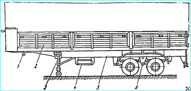
Two-axle semi-trailer (Fig. 1) for general purposes, with a load capacity of 20 tons, with an open platform, with metal folding side and rear sides
To protect cargo from precipitation, an awning with a frame is installed. The semi-trailer is designed for operation on roads of categories I and II.
The diameter of the coupling kingpin is 50.8 mm.
The main towing vehicle for towing is the MAZ-504V tractor unit.
The semi-trailer frame is welded and consists of side members, side beams, cross members, a safety buffer and brackets for fastening the units.
The best ratio of bending strength to weight is provided by I-section side members, and the use of welded side members, compared to rolled ones, while ensuring strength and reducing weight, makes it possible to reduce the cross-section in places with lower stress.
Based on these considerations, the side members of the MAZ-5205A semi-trailer are made.
The narrowing of the side members in height above the fifth wheel coupling of the tractor is compensated by a rolling plate, which increases the rigidity and strength of the frame section.
In addition, the very place of transition from the narrowed part of the side member to the middle one is reinforced by welding a lining to the lower shelf.
The cross members above the rolling plate are welded both to the plate and to the side members, thereby eliminating the possibility of the plate bending due to the fifth wheel coupling of the tractor.
A socket for attaching the kingpin is welded between the cross members to the rolling plate.
The middle cross members, which serve to connect the side members and ensure uniform distribution of torsional stress, simultaneously impart rigidity to the side member walls and serve to attach the floor.
The cantilevered, stamped cross members of variable height connect the side members with the side beams of the frame, for which a rolled channel profile with a cross section of 140x60x6 mm made of 09G2 steel is used.
Brackets for attaching support devices, suspension, brake and electrical equipment.
A safety buffer and towing eyes are installed at the rear of the frame.
The front cross member of the frame is stamped, channel section, made of a spherical shape to increase the strength of the fastening and rigidity of the front side of the platform.
Before the narrowing of the side members in height, a frame for fastening stationary support devices is welded to them, consisting of a cross member and longitudinal transverse braces.
Brackets for fastening the spare wheel holder are welded to the right side member in the front part.
Two sockets are welded to the side beams for installing the platform posts, the sides of which are attached to the beams, front and rear cross members.
The floor of the platform is attached to the beams and cross members of the frame.
Thus, the frame is also the base of the semi-trailer platform.
Main load-bearing parts frames are made of low-alloy steel, which ensures good weldability and performance in all climatic zones.
In the middle part of the frame (along the length), the crossbar is welded to the side members only to the walls of the latter, which ensures a reliable connection and torsional performance.
Towing hooks are welded to the rear part, on the inside of the side members.
The front part of the semi-trailer frame is made with connection dimensions according to GOST 12105-74, i.e. the contour from the axis of the coupling kingpin forward fits into a radius of 1680 mm, and from the kingpin to the support devices goes beyond the radius of 1900 mm, which ensures the adhesion of the MAZ-5205A semi-trailer to all two-axle truck tractors.
The kingpin of the semi-trailer is pressed into the socket and secured with a crown nut and cotter pin. The diameter of the kingpin for the grips of the fifth wheel device of the tractor is 50.8 mm.
Maintenance and repair of the frame is similar to the maintenance and repair of the frame of the MAZ-5245 semi-trailer.
Suspension device
Due to the increase in the speed of mainline road trains and a significant increase in load capacity, the requirements for suspension of semi-trailers.
An important role is played by the smoothness of the ride, provided by the suspension for the safety of the transported goods at various degrees of loading.
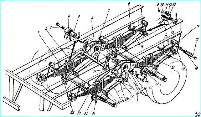
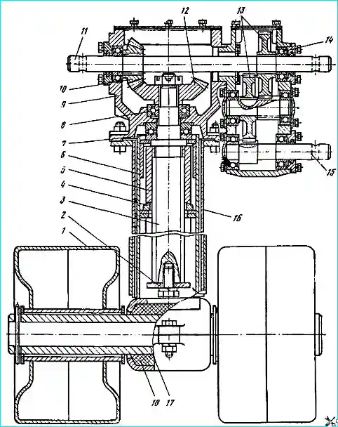
The specified requirements are met by a four-spring balance beam suspension installed on two-axle semi-trailers (Fig. 2).
the use of asymmetric semi-elliptical springs 1 with sliding ends, allowing the most uniform change in suspension stiffness depending on the degree of loading and unevenness of the road surface, required the introduction of reaction rods 14, 29 to transmit pushing forces to the wheels and braking moments from them to the frame.
The uniformity of the load on the axles is ensured by an equal-arm balancer 26, which includes the short ends of the springs.
When loading the semitrailer to the maximum permissible overall height, lateral stability is achieved by installing rubber buffers 8 above each spring and a stabilizer 2.
The spring bracket and balancer brackets are stamped and welded, welded to the lower shelf of the side members.
The ends of the springs slide between replaceable liners 17, 20, 27 and bushings 19, in the brackets and balancer 26, while to prevent cases of springs slipping, the third main leaf is bent at the ends.
Replaceable liners are made of steel St. 3, and are designed to protect the side cheeks of the brackets and balancers from abrasion and to reduce wear of the upper main leaf of the springs.
The springs are mounted on cushions welded to the axles, and are secured using two stirrups 32 through the upper pads 21, 33 of the springs and the lower pads 22 and 35.
The reaction rods are attached to the lower pads and brackets of the balancer and springs using a pin 10, nut and cotter pin.
In addition to transmitting pushing forces, the reaction rods are designed to adjust the position of the wheel axles relative to the longitudinal axis of the semitrailer, for which purpose one of the rods on each axle is made adjustable.
The complex kinematics of the movement of the reaction rods during suspension operation is provided by spherical ball bearings 16 (ШС-50), pressed into the heads of the reaction rods and fixed with retaining rings 15.
The horizontal movement of the rod head on the axis is limited by bushings 11.
The seals 13, fixed with spring rings 12, protect the bearings from contamination.
The rubbing parts of the reaction rods are lubricated through grease nipples 9 on the mounting axes.
The equal-arm balancer 26 is stamped, welded, is attached to the bracket by a pivot on the axis 23 and rotates freely in bronze bushings 25.
To prevent abrasion of the bracket cheeks, gaskets 24 are installed on both sides of the balancer.
The bushings and the balancer axis are lubricated through a grease nipple 22 installed on the axis.
The balancer axis is fixed with nuts 6 and a lock washer 7, while the balancer should rotate with the force of the hand.
The stabilizer 2 is installed to increase the lateral stability of the semitrailer when turning and changing lanes.
The stabilizer is a shaft with curved ends, which are attached to the upper linings 33 of the rear springs by means of pins 3.
It is attached to the frame of the semitrailer through levers 4 with a cover 34 in rubber-metal bushings 5.
With the simultaneous and identical travel of the left and right sides of the suspension, the stabilizer rotates in the levers and does not affect the operation of the suspension.
With a difference in the travel of the right and left sides, the end of the stabilizer is twisted relative to the middle part of the shaft, due to which the rigidity of the suspension increases and the amount of spring travel and, accordingly, the lateral roll of the semitrailer decreases.
Simultaneously with stabilizer, rubber spring travel limiters 8 (buffers) have a significant impact on increasing the lateral stability of the semitrailer.
With increasing loads on the spring, when the semitrailer rolls or when moving uphill, the rubber buffer, reducing the active length of the spring, thereby increases its rigidity.
The greatest efficiency of the stabilizer and spring buffer is manifested when transporting goods with a high center of gravity.
Maintenance of the suspension consists of checking the tightening of all threaded connections.
In order to prevent shearing of the center bolt of the springs, it is necessary to periodically tighten the nuts 31 of the U-bolts, providing a tightening torque of 60-65 kgcm, while the semitrailer must be fully loaded.
This requirement must also be met in order to reduce tire wear, which increases when the axles are skewed.
Loosening of the fastening of the stepladders also leads to an increase in dynamic loads on the bearings 16 of the reaction rods 14, 29, to premature wear of the seating surfaces and destruction of the bearings.
A change in the position of the axes can also lead to loosening the nuts of the bolts that fix the position of the rod of the reaction rod 29 in the heads 28 and 30.
A creaking sound in the springs indicates a lack of lubrication between the sheets, which increases interleaf friction and increases wear of the sheets.
To prevent creaking in the springs during maintenance, the sheets should be coated with a thin layer of grease at the points of contact with each other.
The pins and axles of the suspension parts fastening and are subject to wear as they operate, which can lead to dynamic impacts in the joints and premature failure.
To increase the durability of the joints, it is necessary to regularly change the grease, especially in the balancer axles and the torque rod mounting pins, and tighten until axial play is eliminated.
The main reason for the breakage of spring leaves is overloading the semitrailer.
It is necessary to remember that a broken spring leaf does not work and thus increases the load on the remaining leaves, which can lead to breakage of the entire spring.
Failure of the main leaves, through which direct connection with the frame is carried out, is especially dangerous.
Untimely replacement of broken main leaves can lead to axle rotation during movement and an accident.
Repair
For ease of disassembly suspension, it is advisable to place trestles under the semi-trailer frame, having previously unloaded the springs from the dead weight of the frame, for which purpose lift the front part of the semi-trailer with support devices, and the rear part with a jack (from the tractor kit) under the rear buffer.
To remove and disassemble the spring, it is necessary:
- - unscrew the nuts of the tie bolts 18 (see Fig. 2) in the balancer, remove bolts and bushings 19;
- - unscrew nuts 31 of the stirrups, remove the stirrups, upper pads 21 and 33 of the spring;
- - unscrew nuts of the center bolt and clamp bolts, remove bolts and bushings.
During operation, the spring may have: breakage and cracks of sheets, shear of the center bolt, breakage and cracks of the clamps, wear of the ends of the upper main sheet, wear from the ends of the mating sheets, cracks in the stirrups or shear of the thread, shear of the tie bolts in the brackets and balancer.
Spring sheets that have cracks or wear of more than 1 mm must be rejected and can be remade, if possible, into shorter sheets.
When worn out end of the upper main sheet more than 60% of its original thickness, the sheet should be replaced or swapped with the second main sheet.
Sheets with residual deformation (sagged) are straightened to the original size.
Broken center bolts and clamps, as well as spring U-bolts with cracks and stripped threads, are subject to replacement.
Cracks on the clamps can be welded and then cleaned flush with the main surface.
To remove the balancer, unscrew nuts 6 (see Fig. 2) fastening the balancer axles, knock out axle 23, shine gaskets 24 and balancer 26.
After disassembling, the bronze balancer bushings must be cleaned of grease and sanded with emery cloth.
The working diameter of the bushing is 90+0.14 mm (it is permissible to use bushings without repair with a diameter of 90.2 mm). Clean the balancer axle from rust and bronze galling.
The upper and side replaceable liners in the spring brackets and balancer are subject to replacement as they wear out.
If they are not replaced in a timely manner, the walls of the bracket and balancer wear out. Permissible wear of walls by thickness is not more than 2 mm.
If wear is greater, the brackets and balancer are subject to replacement or can be corrected by metal surfacing with subsequent cleaning to the main plane.
To remove the stabilizer, it is necessary:
- - unscrew the bolts securing the covers 34 to the levers 4, remove the covers and rubber-metal bushings;
- - remove the cotter pin and unscrew the nuts of the pins 3 securing the levers 4 to the brackets on the frame, remove the levers, knocking out the pins 4;
- - unscrew the cotter pin and unscrew the nuts of the pins securing the stabilizer shaft 2 to the upper linings 33, remove the stabilizer shaft.
To remove and disassemble the reaction rods, it is necessary:
- - unscrew the cotter pin and unscrew the nuts of the pins 10 fastening the reaction rods 14 and 29, knock out the pins without damaging the threads, remove the reaction rods;
- - remove the retaining ring 15 of the spherical bearing and press out the bearing 16. This operation is recommended only if the bearing is damaged;
- - unscrew the heads 28 and 30 of the adjustable rods 29, releasing the tie bolts.
The rubber buffer 8 is removed and replaced if it delaminates or wears out.
Assemble the suspension in the reverse order.
Before assembly, all parts must be washed in kerosene and blown with compressed air or wiped and lubricated mating parts. Rubber bushings are not lubricated.
During assembly, it is necessary to carefully fasten all parts.
Tighten the spring U-bolt nuts with the springs straightened, providing a tightening torque of 60-65 kgfm, and the axle and pin nuts - until axial play is eliminated. The stabilizer shaft is installed with the cut corners on the heads down.
After assembling the suspension, it is necessary to adjust the position of the wheel axles relative to the longitudinal axis of the semi-trailer, for which:
- - install the semi-trailer on a flat horizontal platform;
- - find and mark the position of the kingpin center on the platform using a plumb line;
- - mark the left and right points on the front part of the first axle beam, remove data from the caliper flanges at a distance of 20 ± 1 mm, measure the distances from the found kingpin center to the marked points. The difference in size should not exceed 2 mm;
- - install the second axle parallel to the first by measuring the distances between them and adjust the axle positions with adjustable reaction rods 29, releasing the tie bolts of heads 28 and 80.
A full turn of the rod lengthens or shortens the reaction rod by 3 mm. After adjustment, tighten the bolts.
The specified adjustment must be performed to ensure minimal wear of the tires during operation and to ensure the alignment of the longitudinal axes of the semitrailer and tractor during straight-line movement.
Axles, hubs, wheels and tires
The semitrailer is equipped with the same axles, hubs, wheels and tires as the MAZ-5245 semitrailer. Air pressure in tires 4.3 kgf/cm²
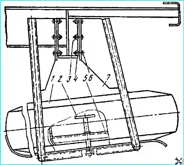
The spare wheel (Fig. 3) is attached to the right side member of the frame using holder 7. The spare wheel is installed on the holder plane and secured using bracket 5 and screw 2.
In order to reduce the effort required to install the spare wheel, it is recommended to use the mounting blades included in the tractor tool kit.
Support device
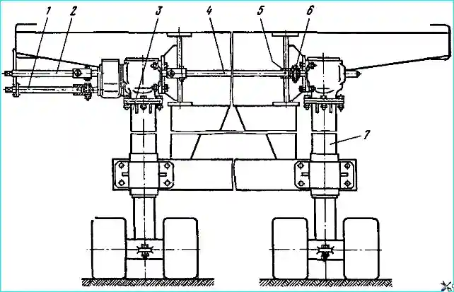
The support device (Fig. 4) is two screw jacks located in the front part of the semitrailer and connected to each other by an intermediate shaft.
The right jack of the support device (Fig. 5) differs from the left one by the presence of an additional two-speed gearbox, which ensures accelerated lifting and lowering of the rollers of the support devices at idle (before the rollers touch the ground), as well as lifting and lowering the semitrailer.
The extreme upper position of the support device stand is limited by nut 5 of the screw and the shoulder of the screw, and the extreme lower position is limited by the limiter 2.
To lift the semitrailer, it is necessary (see Fig. 4):
- - place the semitrailer on a horizontal platform, put the handle on the tail of shaft 2 of the drive and - rotate it clockwise, lowering the rollers of the support device until they touch the ground;
- - put the handle on the tail of shaft 1 of the cargo transmission and, rotating it clockwise, lift the semitrailer. A sharp increase in the force on the handle indicates that the support device post is in the limit position.
Lowering the semitrailer or setting the support device to its original position is carried out in the reverse order.
Operation in direct gear after the rollers touch the ground (regardless of whether the semitrailer is loaded or unloaded) is not allowed.
In exceptional cases, when it is necessary to uncouple the tractor from the semitrailer on an uneven surface (if, when lowering the support devices, the rollers of the left support device touched the ground, and the right support device did not reach the ground by more than 50 mm), the semitrailer is equipped with the possibility of uncoordinated operation of the support devices.
To lower the rollers of the right support device, it is necessary:
- - remove pin 6 (see Fig. 4) and, turning the handle, lower the right support device until the rollers touch the ground, then install the pin in its original place and cotter pin it;
- - by rotating the handle shaft 11 of the drive, raise the semitrailer to the required height.
If the rollers of the right support device have touched the ground, and the left one has not reached the ground by more than 50 mm, it is necessary to lower the rollers of the left support device in the following order:
- - remove pin 6 and, rotating the handle shaft 1, raise the righte support device by a value equal to the distance between the ground and the rollers of the left support device, then install pin 6 in place and cotter pin it;
- - turning the drive shaft with the handle, lower the support device until it touches the ground, and then raise the semitrailer to the required height.
After coupling the semitrailer to the tractor, it is necessary to raise the rollers of the support devices to the transport position, aligning them using the method described above.
It is not allowed to move the semitrailer with extended support devices, as well as to roll the semitrailer on the rollers of the support device.
Maintenance of the support device consists of timely lubrication and checking of bolted connections.
In winter, when parking a semitrailer without a tractor, to prevent freezing and subsequent breakage of the support devices, it is recommended to put wooden blocks under the rollers linings.
Possible malfunctions of the support device and how to eliminate them
- High force on the drive handle or the shaft does not rotate
Lack of clearance in the gear engagement - Adjust the clearance
Lack of play in the thrust bearing due to excessive tightening of the nuts - Adjust the bearing tightening
Repair
The support device is usually disassembled to replace worn or damaged parts, as well as to add or replace grease.
To disassemble the support device, it is necessary:
- - install the semi-trailer with the front part on the trestles, disconnect the support devices from the semi-trailer and remove the rollers;
- - through the hole in the shoe of the rack 6 (see Fig. 5) unscrew the bolt of the limiter 2 of the support device, remove the limiter and, rotating the drive shaft 11 clockwise, remove the rack 6 from the housing 16;
- - remove the crankcase cover 9 and the bearing caps of the drive shaft 11, take out the drive shaft, having first removed the retaining ring;
- - unscrew the nut of the screw 3 of the jack, remove the bevel gear 12 and lightly tap the end of the screw from above with a hammer to remove it from the housing 16, remove the thrust bearings.
After disassembling, wash all parts, blow with compressed air, lubricate generously and assemble the support device in the reverse order.
After assembly, check the engagement of the gears, adjust with adjusting shims if necessary, fill the crankcase cavity with TSIA-TIM-201 grease and close lid.
Brake system
The semi-trailer is equipped with two brake systems: service and parking. Both systems act on the pads of the wheel brake mechanisms.
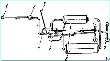
The brake mechanism drive of the service brake system is pneumatic, single-wire (Fig. 6), and operates when the brake pedal is pressed in the tractor cab.
The parking brake drive is mechanical.
The design of the wheel brake mechanism of the MAZ-5205A semi-trailer is fundamentally no different from the design of the wheel brake mechanisms of the MAZ-8926 trailer.
The difference lies in the increased width of the brake drums and brake linings, a longer expander cam and a cast caliper fixed to the flange of the wheel axle.
The design of the pneumatic brake drive units and the principle of its operation are the same as those of the MAZ-8926 trailer.
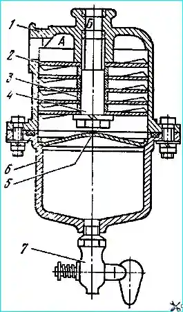
The original unit is the oil-moisture separator (Fig. 7), which performs the function of cleaning the air supplied by the compressor to the pneumatic system of the semi-trailer from oil and water vapor.
The oil-moisture separator is installed in front of the air distribution valve in the supply line.
The impellers 2 of the oil-moisture separator are attached to the body by means of spacer bushings 3 and a tie bolt 4.
Tap 7 is used to drain the condensate.
The air is cleaned from oil and moisture vapor in the oil-moisture separator due to the action of centrifugal forces.
Air through the hole "A" it enters tangentially to the inner surface of the housing 1 and, passing through the holes of the impeller 2, acquires rotational th movement.
The centrifugal forces that arise during the rotational movement of the air flow and the change in its direction throw particles of oil and moisture to the walls of the housing and to the surface of the reflector 5.
Moisture and oil flow from these surfaces through the holes in the reflector into the tray 6.
The purified air through the hole "B" enters the air distribution valve, and then into the air cylinders.
Two air cylinders with a capacity of 23 and 42 liters are installed on the semi-trailer, in which a reserve of compressed air is created, supplied by the compressor of the tractor.
The cylinders are attached to the frame by means of clamps and pads. To remove condensate, there is a tap at the bottom of each cylinder, which should be opened at the end of the working day.
The parking brake drive is similar to the drive of the MAZ-8926 trailer. The parking brake handle is located on the right side of the semitrailer.
The parking brake ensures braking of the semitrailer with a full load in the uncoupled state on a dry road with a hard surface on a slope of no more than 20%.
The force on the parking brake handle during full braking of the semitrailer should not exceed 40 kgf.
Maintenance of the brake system units is the same as for the MAZ-8926 trailer.
Maintenance of the moisture-oil separator consists of periodically disassembling it and washing the parts in gasoline and blowing them with compressed air.
During assembly, pay attention to the correct installation of impeller 2.
After assembly, it is necessary to check the tightness of the moisture-oil separator under a pressure of 5 - 6 kgf/cm2 air leakage is not allowed.
Repair of brakes of MAZ-5205A semitrailer is similar to repair of brakes of MAZ-8926 trailer.
Below are recommendations for restoration of two distinctive parts: caliper and bracket of brake chamber.
Brake caliper is made of steel casting 40L. It is restored when the hole for the brake pad axle and the hole for the brake chamber bracket are worn out.
When the hole for the brake pad axle is worn out to a size greater than 32.1 mm, a repair sleeve is installed.
To do this, the worn hole is drilled to Ø 35.8 mm, a 1X45° chamfer is countersunk on the side of the attachment to the brake shield caliper and the hole is reamed to Ø 36+005 mm.
Then a repair sleeve is pressed into the machined hole, a hole is drilled in the sleeve Ø 8.7 mm through the hole in the caliper for the brake pad axle lock screw and an M10x1 class thread is cut. 2 in the bushing hole.
Countersink the chamfer 1x45° in the bushing hole on the side of attachment to the brake shield support and ream the hole in the bushing to Ø 32+005 mm.
The holes for the brake chamber bracket, worn to a size of 56.1 mm, are also restored by installing a repair bushing.
Drill out the worn hole to Ø 59.8 mm, countersink the chamfer 1X45° on the side of attachment to the brake shield support and ream the hole to Ø 60+0.05 mm.
Press the repair bushing into the machined hole, countersink the chamfer 1 x 45° in the bushing hole on the side of attachment to the brake shield support and ream the hole to Ø 56+006 mm.
When machining the holes for the brake shoe axle and for the brake chamber bracket, the surface of the hole Ø 172 +0.08 mm is taken as the base.
The axes of the holes for the brake chamber bracket and for the brake shoe axle, as well as the mounting hole Ø 172 +0.08 mm must be parallel to each other and perpendicular to the mating surface with the trailer axle flange with an accuracy of 0.1 mm over a length of 100 mm.
Brake chamber bracket. The bracket tube is made of 35 steel, and the bushings for the bearing journals of the expanding cam are made of KMC-3-1 bronze.
The bracket is restored when the holes in the bushings for the bearing journals of the expanding cam and the holes in the flange for the mounting bolts to the caliper are worn out, the bearing flange is bent and the welds are damaged.
When the holes in the bushings for the bearing journals of the expanding cam are worn out to a size greater than 38.10 mm, the bushings are replaced.
To do this, press out the worn bushings and press in new ones: one on the side of the socket under the sealing rings flush with the end of the socket and the second flush with the end of the bracket.
Then install the bracket in the jig and ream the holes in the bushings to Ø 38 on a vertical drilling machine mm.
The runout of the mounting surface in the caliper relative to the axis of the surfaces of the bushing holes for the bearing journals of the expanding cam should not exceed 0.1 mm.
If the holes in the bearing flange for the mounting bolts to the caliper are worn to a size greater than 15.3 mm, they are drilled to Ø 17.0 mm, welded with a continuous seam using a UONI-13/45 electrode Ø 3 mm, both surfaces of the bearing flange are turned down to remove the deposited metal and holes Ø 15 mm are drilled, having previously marked the centers of the holes using a template.
The plane of the flange should be perpendicular to the surface of the holes in the bushings for the bearing journals expansion cam with an accuracy of 0.2 mm over a length of 100 mm.
Damaged welds are restored by back-welding them at the damaged points with a UONI-13/45 Ø 3 mm electrode.
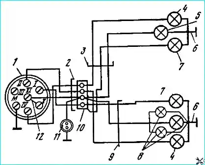
The electrical equipment of the semi-trailer is made according to a single-wire circuit (Fig. 8). The semi-trailer has a seven-pin socket for connection to the tractor.
The semi-trailer platform (Fig. 9) is flatbed.
The rear and side sides open downwards on hinges, the side posts are removable.
The front side is installed permanently. The awning frame and awning are installed on the platform.
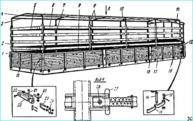
The platform floor is wooden, the sides are metal. The awning frame is made of tubular profiles with wooden gratings.
The platform base is the semi-trailer frame, on which the floor cassettes are installed.
The cassettes are assembled from 34 mm thick boards, connected to each other with a tongue and groove joint, enclosed at the ends in a stamped square with a cross-section of 85x29x2 mm.
The boards are fastened to the fittings with M6 bolts. The cassettes consist of two parts - right and left, and are joined during assembly along the longitudinal axis of symmetry of the platform.
The outermost floor boards have a milling that ensures installation under the profile of the side beam of the frame.
The cassettes are fastened to the frame crossbars with M8 bolts through the end fittings. The floorboards on the frame are arranged in the longitudinal direction and are attached to the frame crossbars with M8x55 bolts.
The front three boards, processed according to the semicircular profile of the front crossbar of the frame, are installed across the frame and tucked under the front crossbar. They are attached with M8 bolts to the angles on the frame.
To provide access to the removable kingpin of the semitrailer, there is a hatch in the front floor cassette, covered with a plate. The plate is attached to the boards with M6x30 screws.
The side beam of the frame, the upper shelf of which is in the same plane as the floorboards, has five holes with welded tubular guides for installing the awning frame posts.
The side boards are composed of three parts, each 3070 mm long, metal, welded, and consist of a 1.5 mm thick corrugated panel with a longitudinal arrangement of corrugations.
The board is rigid due to the frame, welded from 40x40x2 square pipes with two vertical posts.
Four stamped loops are welded to the lower pipe of the frame, to which the boards are hung using axles.
A reinforcement with windows for installing add-on boards is welded to the upper pipe of the frame.
Clamps are welded to the board panel opposite the windows. The size of the window and bracket in the clear is 72x34 mm.
A plate with arched loops is welded to the side panel at a distance of 410 mm from above, through which the platform awning is attached. The distance between the loops does not exceed 200 mm, the clear loop size is 35x13 mm.
Below the loops, three stamped hooks for attaching the awning tension cord are welded to the panel between the posts.
At a distance of 285 mm from above, brackets with ears for attaching the clamp 15 of the lock are welded to the side panel near the outer posts of the frame.
A pin 14 with a locking bar is attached to the bracket on a chain.
The clamp 15 of the lock, fixed on the post 18, is inserted between the ears into which the pin 14 is inserted and fixes the clamp.
The pin is prevented from falling out by a locking bar, which rotates eccentrically on a rivet in the groove of the pin 14 and, under its own weight, always tends to take perpendicular position relative to the pin.
A stamped angle is welded to the lower edge of the side, covering the gap between the sides and the frame, preventing moisture from getting inside the platform.
The rear side side differs from the front side in that it is attached to the outer pillar, adjoining the rear side, a bracket for the step-ladder lock is welded at a distance of 260 mm from above.
The rear side 1 differs structurally from the side sides by its locks, two brackets welded to the upper reinforcement for ease of climbing into the body, and a supporting folding step on the inside of the side.
When the rear side is open, the step rotates around the axis under its own weight and is installed perpendicular to the side panel.
The rear side lock is of the step-ladder type.
The locking occurs due to the tension of the step-ladder 25, secured to the bracket on the side side on the axis 24 using nuts.
The nuts not only secure the step-ladder, but also adjust it relative to the axis (lengthening or shortening).
The handle 23 of the lock is secured by the axis to the ears of the bracket lock welded to the side pillar of the tailboard.
Turning the handle perpendicular to the side panel, we grab the stepladder 25 of the side board with the curly cutout of the handle and then return the handle 23 to its original position, pressing it tightly against the side panel.
In this case, the axis of the stepladder will go beyond the center of the fastening axis and, due to the eccentricity, will ensure reliable locking of the lock.
Additional fixation of the handle 23 in the closed position is carried out by the lock 20, which is secured in the handle by the finger 21 and is pressed away from the handle by the leaf spring 22.
The folding sides are fastened with pins through the hinges to the stamped ears 16.
The ear is fastened to the frame beams with two bolts, while the position of the ear along the beam is adjusted due to the elliptical holes on the beam.
To protect the parts and units of the tractor and semi-trailer, as well as the drop sides, rubber stops 19 are bolted onto the frame beam and the rear cross member.
The front semi-circular side is similar in design and mounting method to the front side of the MAZ-5245 semi-trailer.
The side sides are connected to each other and to the front side via the front pillar and middle pillars. The front pillar is attached with M10 bolts to the front side panel and frame beams.
The pillar has an omega-shaped unequal-flange section.
One of the shelves is attached to the front side, the second goes behind the side side from the inside of the platform.
The middle pillar 18 has an equal-arm omega-type section, both shelves of which go behind the side sides, closing the gap between the side and the pillar.
At the bottom, the middle pillar has a slope, with which it enters the socket on the side beam of the frame.
On the inside, the pillar is reinforced with a welded metal strip, creating a box-shaped section in the most stressed places.
Square cutouts are made in the outer corners of the pillar, into which the brackets 15 of the lock are inserted. The brackets are fastened with pin 13 to the ears welded to the posts.
To increase the transverse rigidity of the platform and to protect the transported cargo from shifting in the longitudinal direction, tension chains are installed between the opposite posts 18, secured to the brackets of the posts on one side with a hook, and on the other - with the same lock as on the MAZ-5245 semitrailer.
")

")
")
")
")
")
")
")