Removing the connecting rod and piston group
Number the connecting rods and connecting rod caps in accordance with the cylinder number on the side opposite the camshaft (if this is not provided for by the design)
Remove the connecting rod lower head caps.
Remove the lower connecting rod lower head liners (650.1004059).
Arrange the parts in the correct order.
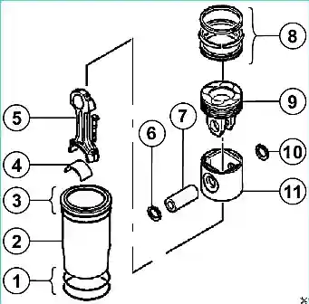
Remove connecting rod with piston assembly.
Remove the upper connecting rod lower head liners (650.1004058).
Arrange the parts in the correct order.
Disassembling the connecting rod and piston group
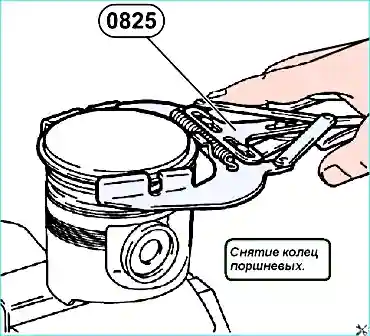
Remove the piston rings (8) using tool 0825 (see Fig. 2).
Remove the retaining rings (6, 10).
Press the pins (7).
Separate the heads pistons (9) from skirts (11).
Checking the crank mechanism parts
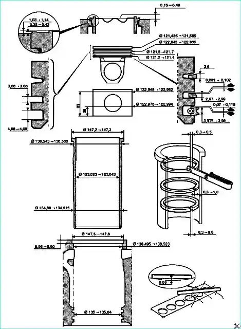
Piston: diameter, pin and its seating surface, piston ring grooves.
Piston rings: thickness, clearance in the piston ring groove, clearance of the retaining rings.
Connecting rods: straightness and straightening, liners.
Assembly of the connecting rod and piston group
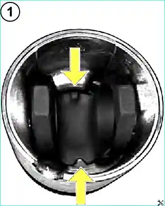
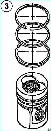
- 1. Mount the piston head with the skirt, orienting the bosses opposite each other (see Fig. 3), (650.1004013 - composite piston assembly).
- 2. Assemble the piston with piston rings using device 0825 (see Fig. 2):
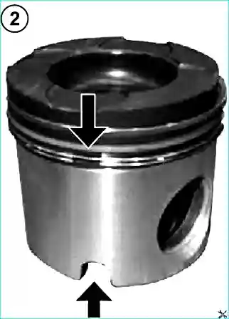
A set of piston rings is installed on the piston:
- - the first compression ring has a double-sided trapezoid in cross-section, the working surface is coated with chromium ceramics
- - the second compression ring is of rectangular cross-section (minute);
- - a box-type oil scraper ring with a twisted expander, the working edges are coated chrome
- - upper compression ring (650.1004030),
- - second compression ring (650.1004032),
- - oil scraper ring (650.1004034). The piston oil scraper ring lock should be located on the side of the recess on the piston skirt (see Fig. 4).
The locks of the 3 piston rings should not be on the same line (see Fig. 5).
3. Lubricate the piston pin (650.1004020) and connecting rod bushing with oil.
- 4. Assemble the piston with the connecting rod and pins so that the groove for the liner tab is on the side of the recess for the nozzle on the piston skirt (see Fig. 6).
- 5. Install retaining rings (650.1004022).
Installing the connecting rod and piston group
- 1. Install the upper and lower liners of the lower connecting rod head and lubricate the working surface with engine oil.
- 2. Lubricate the working surface of the cylinder liners with engine oil.
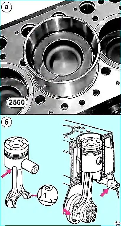
- 3. Install the connecting rod assembly with the piston in the cylinder block using device 2560 (see Fig. 7 a).
- 4. The groove on the piston skirt for the piston cooling nozzle must match the location of the nozzle itself, and the numbers on the connecting rods must be on the side opposite the camshaft (see Fig. 7 B).
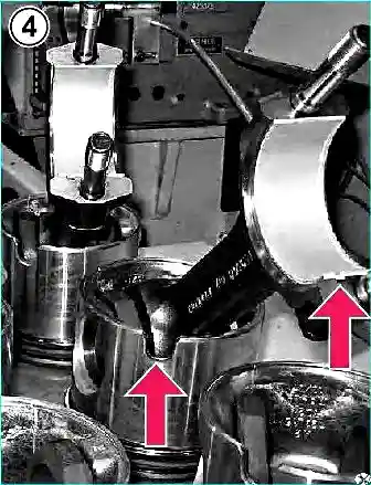
5. Install the connecting rod lower head caps in accordance with the numbering.
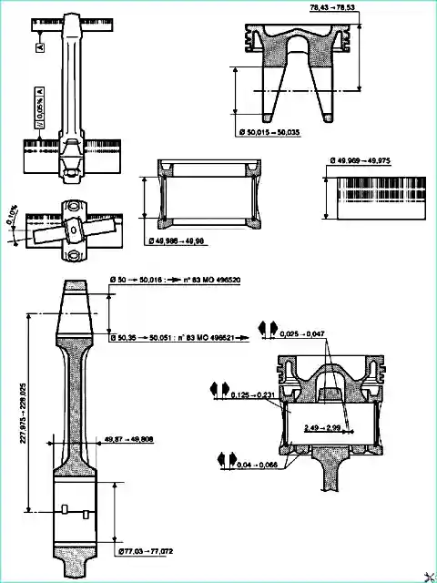
- 6. Tighten the connecting rod cap fastening nuts:
- - ensure the first tightening by 80 ± 8 Nm;
- - ensure the second tightening by 180˚ ± 6˚.
- 7. Check the clearance between the connecting rod caps and the crankshaft journals
Crankshaft tightening torques
Cap fastening bolts crankshaft main bearings:
- - preliminary tightening torque: 80 ± 8 Nm
- - final tightening torque: 180 ± 6 Nm
Flywheel mounting bolts with manual transmission. Bolts are used only 2 times. Installing the bolts for the third time is not allowed.
- - preliminary tightening torque: 60 ± 6 Nm
- - final tightening torque: 120 ± 6 Nm
Connecting rod cap fastening bolts:
- - preliminary tightening torque: 80 ± 8 Nm
- - final tightening torque: 90 ± 6 Nm
Damper fastening bolts on the hub:
- - preliminary tightening torque: 50 ± 5 Nm
- - final tightening torque: 120 ± 12 Nm
Pulley fastening bolts damper 67 ± 7 Nm


