Repair of water pump YaMZ-2Z6NE, HE2, BE, BE2 of MAZ car
A typical malfunction of the water pump is water leakage through the impeller seal as a result of wear of the textolite ring
A malfunction of the stuffing box seal is indicated by water leaking from the drainage hole on the water pump body, which can be eliminated by turning the textolite ring over with the reverse side (unworn) facing the end of the sleeve pressed into the body, or by replacing the ring while simultaneously replacing the rubber cuff.
Clogging the drain hole to eliminate oil seal leakage is not allowed, since water leaking from the pump gets into the bearings and damages them.
To repair the stuffing box you need:
- - remove the water pump from the engine; unscrew the nuts securing the housing cover, remove the cover and gasket;
- - holding the roller by the pulley from turning, unscrew the cap nut and use a puller to remove the impeller from the pump shaft, remove the locking ring of the impeller seal and remove all the seal parts from it.
The suitability of the oil seal parts is determined by external inspection. The textolite ring should not have any chips or cracks on the working surface.
Minor scuffs and risks can be eliminated by grinding in the ring. The oil seal seal must be elastic, without tears, and fit tightly to the shaft and textolite ring.
Assemble the impeller oil seal in the following order:
- insert the oil seal spring into the impeller housing, then the rubber cuff assembled with the inner and outer races, the textolite and oil seal retaining rings.
After installing the locking ring, the textolite one should move freely along the grooves of the impeller when pressed by hand and return to its original position under the action of a spring.
The part of the pump shaft on which the rubber cuff sits must be lubricated with soap before installing the impeller, and the end of the bushing in contact with the textolite ring must be lubricated with a thin layer of graphite lubricant.
This eliminates the possibility of lifting the working surface of the cuff and improves the quality of lapping of the working surfaces of the textolite ring and the end of the bushing.
After installing the impeller in place, the cap nut securing the impeller must be tightened as far as possible and secured with a washer.
When completely disassembling the pump to replace the bearings and shaft, the impeller is removed from the pump shaft, as indicated above;
- - unscrew the pulley mounting nut and remove the pulley from the pump shaft using a puller;
- - unscrew the fastening screws and remove the bearing cover;
- - remove the roller assembly with bearings and bushings from the pump housing.
If there are cracks of any size and location, the housing is not repaired, but replaced. During repairs, felt seals are replaced with new ones, having previously been impregnated with lubricant.
Assemble the pump in reverse order. The housing cavity between the ball bearings must be filled with Litol-24 or CIATIM-201 lubricant.
After assembly, you need to add grease through the oiler until grease appears from the inspection hole. After assembly, the pump shaft should rotate freely, without jamming.
When installing the pump on the engine, it is recommended to replace the gasket between the pump flange and the timing gear cover.
The mating surfaces of the pump flange and the roof of the distribution gears must first be cleaned of the remains of the old gasket, and the new one must be lubricated on both sides with a sealing, non-drying paste.
DISASSEMBLY AND ASSEMBLY OF THE WATER PUMP
- 1. After loosening the water pump drive belt tensioner, remove the belt from the water pump pulley.
- 2. Drain the engine and radiator coolant.
- 3. Remove the inlet pipe from the water pump.
- 4. After unscrewing the fastener, remove the water pump from the engine, carefully without damaging the gasket.
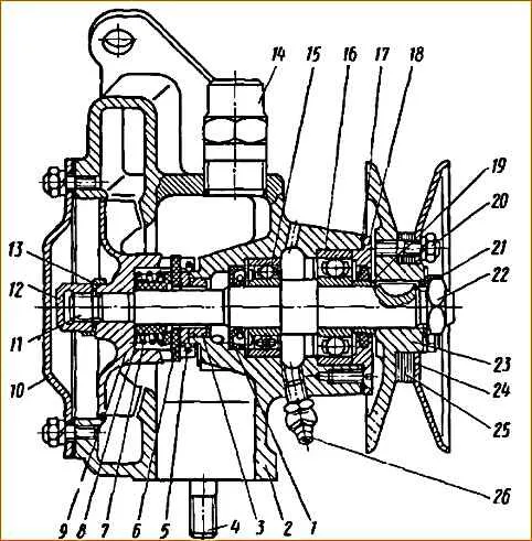
- 5. Unscrew nuts 14 (Fig. 2) of pipe 8.
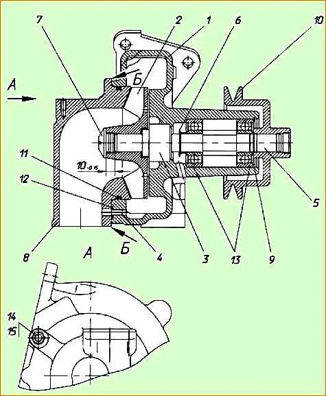
- 6. Lightly tapping the protruding parts of pipe 8 in the direction of arrows B, remove the said pipe from pump housing 1.
- 7. Secure impeller 2 (or pulley 10) from rotation with shaft 5.
- 8. Unscrew plug 7 from the threaded hole of the impeller 2.
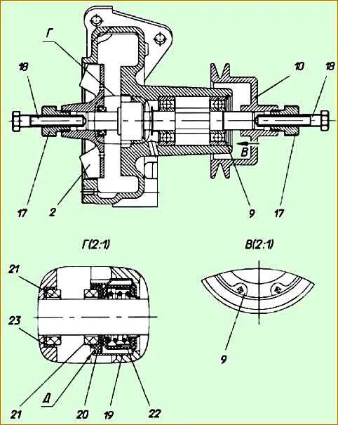
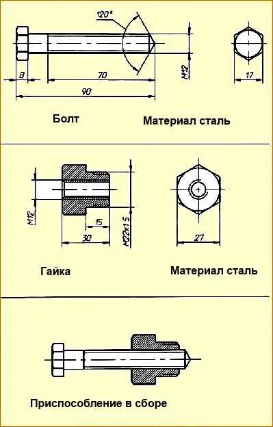
- 9. Screw the nut 17 of the puller into the threaded hole (M22 x 1.5) of the impeller 2 (Fig. 3, 4) and, screwing in the bolt 18, press the impeller 2 from the shaft 5.
- 10. Bend the “whiskers” D of the mechanical seal housing 19 (Fig. 3) and remove the cuff 22 with the spring and frame assembly.
- 11. Using a puller, press pulley 10.
- 12. Remove retaining ring 9 from the groove of pump housing 1.
- 13. Press shaft 5 with water release valve 6 and bearings 13 out of housing 1.
- 14. If the brass body 23 of the mechanical seal is not damaged, it can not be removed from the body 1 and disassembly of the pump can be considered complete.
WATER PUMP ASSEMBLY PROCEDURE
- 1. Wash all pump parts and dry with compressed air.
- 2. Press bearings 13 and water dispenser 6 onto shaft 5 (Fig. 2). In this case, it is necessary:
- - pre-lubricate shaft 5 with diesel oil;
- - install bearings 13 so that the sealing washers are on the outside;
- - apply pressing force to the inner ring of the bearing.
- 3. Fill the entire cavity between the bearings with Litol-24 grease (60...70 g).
- 4. Press the shaft assembly with bearings and water release into housing 1 until it stops. In this case it is necessary:
- - pre-lubricate the housing bore 1 under the bearings with clean engine oil;
- - apply pressing force to the outer ring of the bearing.
- 5. Install 1 retaining spring ring 9 into the housing groove.
- 6. Press pulley 10 onto shaft 5 until it stops. In this case it is necessary:
- - pre-lubricate the shaft with clean engine oil;
- - provide a fixed stop for the opposite end of the shaft.
- 7. Install the mechanical seal parts into the brass body 19 (Fig. 4);
- - rubber cuff 22 assembled with a spring and spring frames;
- - reinforced cuff 20 and sealing sleeve 21.
- 8. Install the rubber cuff 23 and the sealing sleeve 21 into the impeller 2. In this case, it is necessary:
- - first put the cuff 23 on the sealing sleeve 21;
- - apply a thin layer of lubricant to the impeller bore 2 and to the outer surface of the rubber cuff 23;
- - take the cuff assembly with the bushing with both hands and, applying force to the end of the sealing bushing, insert these parts into the impeller bore until it stops, avoiding distortions.
- 9. Press impeller 2, complete with cuff and sealing sleeve, onto shaft 5 (Fig. 2). In this case it is necessary:
- - pre-lubricate shaft 5 with clean engine oil;
- - provide a fixed stop for the opposite end of the shaft;
- - install the impeller on the shaft in a size of 10-0.15 mm (Fig. 2) between the end of the shaft and the end of the impeller hub; for this, when pressing, it is necessary to install a disk with a diameter of no more than 13 mm and a height of 10-0 on the end of the shaft, 15
- 10. Secure impeller 2 (or pulley 10) from rotation.
- 11. Screw plug 7 into the threaded hole of the impeller 2 until it stops;
- 12. Install 1 bushing 4 and rubber ring 12 into the body.
- 13. Install rubber ring 11 into the groove of pipe 3, preventing it from twisting.
- 14. Press pipe 3 into the bore of body 1 until it stops. In this case it is necessary:
- - pre-lubricate the bore in the body 1 ring 11 with a thin layer of Litol-24 lubricant;
- - the studs on body 1 must fit freely into the mounting holes of pipe 8.
- 15. Secure the pipe with 3 nuts 14 and spring washers 15.
- 16. Check the quality of assembly by rotating shaft 5 by pulley 10. The rotation of the shaft should be free, without jamming.
")

")
")
")
")
")
")
")