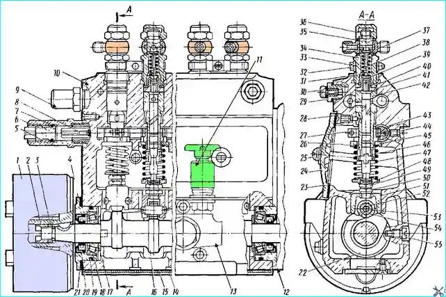
The high-pressure fuel pump (HPFP) is a plunger type, driven by the camshaft through the fuel pump drive gear
The pump has eight pump sections, combined in a common aluminum housing 10 with their drive from a common camshaft 16.
Together with the high-pressure pump, this unit combines an automatic injection advance clutch, which is fixed to the front end of the camshaft, a speed controller located in the housing 12, and a fuel priming pump 13.
The main working element of each pump section is a plunger pair that supplies fuel to the injector and consists of a plunger 46 and a sleeve 52.

Fig. 1. High-pressure fuel pump: 1 - automatic fuel injection advance clutch; 2 - ring nut; 3 - spring washer; 4 - bearing cover; 5 - sleeve; 6 - limit screw; 7 - sealing ring; 8 - rack; bypass valve; 10 - housing; 11 - manual priming pump; 12 - speed regulator housing; 13 - priming pump; 14 - lower cover; 15 - cover gasket; 16 - camshaft; 17 - washer; 18 - tapered roller bearing; 19 - sealing ring; 20 - oil seal; 21 - adjusting shims; 22 - camshaft support; 23 - cover gasket; 24 - side cover; 25 - cover fastening screws; 26 - upper plate of the tappet spring; 27 - tightening screw; 28 - plunger sleeve adjusting screw; 29 - housing insert; 30 - air bleed plug; 31 - nipple; 32 - tightening bolt; 33 - nipple cracker; 34 - valve stop; 35 - sealing washer; 36 - cap nut; 37 - connecting nipple; 38 - discharge valve spring; 39 - discharge valve; 40 - gasket; 41 - discharge valve seat; 42 - plunger sleeve; 43 - toothed ring; 44 - lock screw; 45 - ring gear sleeve; 46 - plunger; 47 - pusher spring; 48 - lower plate of pusher spring; 49 - adjusting bolt; 50 - lock nut; 51 - plunger pusher; 52 - roller axis; 53 - roller sleeve; 54 - pusher roller; 55 - lock screw
The plunger and bushing are machined with high precision and mated to each other not by joint lapping, but by selective (selective by size) assembly.
The plunger pair selected at the factory cannot be disassembled in the future: parts are replaced only as a set.
Each fuel pump is equipped with plunger pairs of the same size group.
The lower part of the plunger has two guide projections that enter the grooves of the rotary bushing 45 installed on the plunger bushing.
A toothed ring 43 is fixed to the rotary bushing with a tightening screw, which is in engagement with the rack 8 of the fuel pump.
This rack is moved by the regulator; At the same time, all the rotary bushings rotate simultaneously, and consequently, the plungers in the bushings of all eight pump sections. In this way, the amount of fuel supplied is changed.
The required position of the rack relative to the toothed ring is determined by the locking screw entering the longitudinal groove of the rack.
The angular displacement of the rotary sleeve 45 relative to the toothed ring 43 with the screw 44 loosened regulates the fuel supply by each section of the pump.
Under the action of the spring 47, the plunger with its lower head through the upper plate 26 of the pusher spring is tightly pressed against the head of the adjusting bolt 49 screwed into the plunger pusher 51, the other end of the spring 47 rests on the lower plate 48 installed in the annular groove of the pump body.
The pusher is pressed by roller 54 against the cam of the shaft 16 and is fixed from rotation by the roller axis 52, the projections of which enter grooves on the bores of the pump body. The roller of the plunger has a floating sleeve.
Under the action of the cam of the shaft 16 of the pump and the spring 47, the plunger performs a reciprocating motion in the sleeve.
The adjusting bolt 49, screwed into the plunger, is locked by a lock nut 50 and serves to regulate the start of fuel supply.
A delivery valve 39 is installed on the upper end of the sleeve 42 of the plunger. Pressed against the seat 41 by spring 38.
The delivery valve serves to disconnect the delivery and suction pipelines when the plunger moves down.
Delivery valves, like plunger pairs, are divided into two groups according to hydraulic density.
Fuel pumps are equipped with delivery valves of only one groups.
Disassembly of the valve-seat pair during operation is not allowed, just like the plunger pair.
Axial movement of the cam shaft 16 in the bearings is allowed within 0.01-0.07 mm.
A set of adjusting linings 21 is used to eliminate excessive movement of the shaft.
Rack 8 of the fuel pump moves in guide bushings pressed into the pump housinga.
The end of the rack protruding from the pump is protected by a sleeve 5, into which a screw 6 is screwed, limiting the engine power during running-in. This screw is secured with wire and sealed.
The upper part of the pump body has channels for supplying and discharging fuel, through which it is supplied to the plunger pairs.
Excess fuel is discharged through the bypass valve 9.
The fuel supplied by the booster pump enters through the inlet opening in the plunger sleeve into the above-plunger space.
When the plunger moves upward, the fuel initially flows back into the fuel supply channel until the upper edge of the plunger end blocks the inlet opening.
The fuel begins to compress, and at a pressure of 10-18 kgf/cm², the discharge valve, overcoming the resistance of the spring, rises, and the fuel enters the high-pressure fuel line to the injector.
With further movement plunger 46 upwards, the pressure in the fuel line increases and when it reaches 200 kgf/cm², the fuel is injected into the combustion chamber by the injector.
Continuing to move upwards, the plunger opens the outlet hole in the sleeve with its helical edge, connected to the branch channel.
As the outlet hole opens, the fuel pressure above the plunger decreases sharply, and the discharge valve begins to close under the action of the spring.
As the plunger moves downwards, under the action of the pusher spring, the above-plunger space is filled with fuel and the process is repeated.
The amount of fuel supplied by each section in one plunger stroke is determined by the length of the injection stroke.
The length of the injection stroke is changed by turning the plunger relative to its sleeve, i.e. by changing the position of the helical cut-off edge of the plunger relative to the outlet of the bushing.
Thus, the dosing of the amount of fuel supplied is carried out by changing not the beginning, but the end of the fuel supply.
Repair of the high-pressure fuel pump
Before starting the inspection, the pump must be thoroughly washed, observing the following sequence:
- - wash all external surfaces until dirt is completely removed;
- - unscrew the screws, remove the side and bottom covers of the pump, as well as the regulator cover with all the parts located in it;
- - thoroughly wash the opened internal cavities.
It is recommended to carry out the washing in a unit intended for these purposes using special cleaning solutions (heated to a temperature of 70-90 ° C) of the following composition:
- - for the pump body
- soda calcined 0.1-0.2%
- sodium dichromate 0.05-0.1%
- 2 - for other parts made of non-ferrous metals (brass, bronze, aluminum)
- emulsol - 3.5%
- liquid glass - 0.15%
- 3 - for steel and cast iron parts
- trisodium phosphate - 1.0-1.5%
- sodium nitrate - 0.5-1.0%
- triethanolamine - 1.0 -2.0%
The condition of the parts is carefully inspected through the opened cavities.
Parts that have breakages, chipping and local wear, are subject to replacement or restoration.
Pay special attention to the condition of the tappet springs.
There should be no wear on the governor spring where it engages the levers, and there should be no wear (in the form of radial grooves) from the weight rollers on the end of the governor coupling.
Check the condition of the bearings and camshaft support, as well as the bearings of the speed governor.
In addition, you should check the smoothness of the rack movement when simultaneously turning the camshaft of the pump, as well as the ease of movement of the weights, the governor lever and the linkage bracket.
It is necessary to check and, if necessary, adjust the play of the camshaft by removing the appropriate number of shims from under the front cover, as described below.
Check the amount of clearance in the engagement "pump rack - toothed crown"; with a stationary toothed ring, the rack stroke should not exceed 0.25 mm.
After conducting a control inspection and eliminating the noticed defects, the camshaft cavity, pusher springs and regulator are washed with clean kerosene and the unit is assembled.
After pouring the required amount of oil into the cavities of the camshaft, regulator and injection advance clutch, proceed to determining the technical condition of the unit, for which the high-pressure fuel pump is installed on an adjustment stand.
The main criterion determining the technical condition of the fuel pump is the amount of wear of the plunger pairs.
The assessment of the suitability of the plunger pairs for further operation should be carried out based on the amount of provision of the maximum possible starting fuel supply.
The value of the maximum starting fuel supply that can be obtained by turning the plunger (toothed ring) relative to the sleeve should be at least 180 mm³/cycle at 80 min¹ of the pump camshaft.
In case of failure to provide the specified requirement, the plunger pairs should be replaced with subsequent adjustment of the pump.
The tightness of the discharge valves is checked by pressing them with filtered diesel fuel through the pump supply channel under a pressure of 1.7-2.0 kgf/cm² with the rack position corresponding to the switched off supply.
The check is carried out for 2 minutes, fuel leakage from the connecting nipples is not allowed.
If faults are detected, the pump is disassembled to the extent required by the repair conditions, with a more thorough examination of the condition of the parts and assemblies.
For high-quality repairs, it is of great importance to correctly determine the scope of work on disassembling the pump. It is not recommended to disassemble such units as the plunger pusher.
It is recommended to disassemble and assemble the pump (see Fig. 1) on a device that eliminates deformation of the housing and protects it from damage.

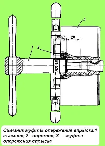
Fig. 2. Injection advance clutch puller: 1 - puller; 2 - ratchet; 3 - injection advance clutch

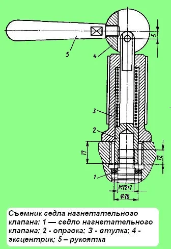
Fig. 3. Puller of the discharge valve seat: 1 - seat of the discharge valve; 2 - mandrel; 3 - sleeve; 4 - eccentric; 5 - handle
The sequence of disassembly is as follows:
- - with a special key, unscrew the nut 2 of the automatic clutch fastening and remove the clutch 1 with the puller shown in Fig. 2;
- - unscrew the three bolts securing the fuel pump and remove the pump and side cover 24;
- - unscrew the cap nuts 36, remove the connecting nipples 37 and the lock crackers 33;
- - unscrew the fittings 31 and remove the valve stops with the springs 38 of the discharge valves;
- - using the puller shown in Fig. 3, remove the seats with the discharge valves from the pump body;
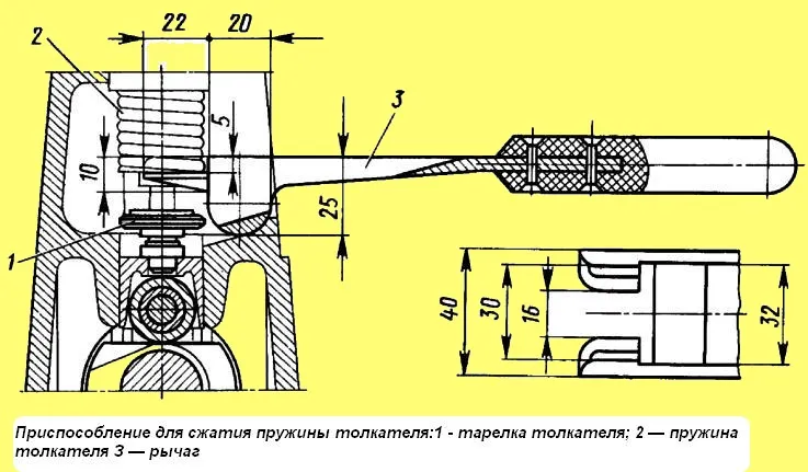
- - using the special device shown in Fig. 4, compress the tappet springs and use tweezers to remove the lower plates of the tappet springs;
- - unscrew the set screws 28 of the plunger bushings and remove the plunger pairs from the pump casing;
- - lightly compress the springs 47 and remove them from the casing together with the upper plates 26, the bushings 45 of the toothed rims and the toothed rims 43;
- - remove the tappets 51 from the guides in the pump casing.
To preserve the factory configuration, it is recommended to disassemble the pump sections, observing the fastening of the components to the sections.
It is not allowed to disassemble the plunger pairs, parts of the discharge valves, as well as the upper and lower halves of the intermediate support of the camshaft.
To remove camshaft of the pump, it is necessary to additionally:
- - disassemble the regulator housing
- - unscrew the locking screw of the camshaft support, press out the keys from both ends of the camshaft;
- - unscrew the screws securing the front bearing cover, remove cover 4 and take out camshaft 16 assembled with the inner bearing races and separators;
- - check the condition of the seals and bearings of the camshaft, if necessary, press out the seals for replacement and press out the bearings using a puller.
Checking the technical condition of the pump parts
Use a magnifying glass to inspect the condition of the discharge valve parts.
Risks and scratches on the conical lapped surfaces, as well as annular wear are not allowed.
Corrosion marks and traces on the end surface of the seat can be eliminated by lapping the seat on lapping plates.
If there are matte spots or shallow lapping marks on the valve shut-off cone or on the seat chamfer, they can be lapped together using fine-grain paste.
If deep longitudinal lapping marks are found on the working surface of the valve relief belt or cone, the valve and seat are replaced as a set.
After inspection and elimination of any detected defects, the valve parts are thoroughly washed with kerosene.
A valve lubricated with clean diesel fuel should fit freely onto the sealing cone under its own weight from any position in height and angle of rotation relative to the seat.
Resistance to valve movement in the seat and seizure are not allowed. The discharge valve assembly is checked for tightness along the cone and the unloading belt.
The valve tightness along the cone is checked with air pressing the valve to the seat under a pressure of 5-6 kgf/cm².
This should be checked by turning the valve approximately 120˚ in three positions relative to the seat.
In each position, the discharge valve is kept under pressure for at least 15 s.
Air leakage, which is determined by the release of air bubbles when the valve is immersed in diesel fuel, is not allowed.
If the seal is insufficient, The valve cone must be lapped against the seat cone with a fine GOI lapping paste.
The condition of the edges and the cylindrical part of the plunger is checked using a magnifying glass.
If deep scratches, matte spots or chips are found on these areas of the surface, then the plunger pair is replaced.
When inspecting the plunger bushing, it is necessary to pay attention to its end.
Scratches and traces of corrosion on the end of the bushing can be removed by lapping the end on lapping plates.
After inspecting and eliminating the detected defects, a preliminary check of the plunger pair is carried out, for this, the parts of the pair are thoroughly washed with kerosene and lubricated with clean diesel fuel.
The plunger, extended from the bushing by 20 - 25 mm, in a vertical position should smoothly lower in the sleeve under its own weight along the entire stroke length at different angles of rotation of the plunger in the sleeve.
Local resistance and seizure during plunger movement in the sleeve are not allowed.
Then the plunger pair is tested for its operability, i.e. for ensuring the above-mentioned value of the maximum possible starting fuel supply.
If there are cracks and stripping of the main threads (for example, under the pump nipple), the housing is replaced.
The plunger is installed in the hole of the pump housing with an initial gap of 0.020-0.063 mm.
When parts are worn, the gap should not exceed 0.2 mm.
The nominal total gap of the roller - sleeve - plunger axis connection should not exceed 0.3 mm. The measurement must be carried out in the assembly.
The camshaft must not have stripped threads and there must be no signs of chipping, pitting wear, cracks or scoring on the surface of the cam profile; the shaft must not have stripped threads.
The maximum permissible clearance in the shaft (cam) - support (middle) connection must not exceed 0.18 mm, with a nominal 0.04-0.93 mm.
The clearance between the rack and the rack bushing must not exceed 0.24 mm. Bushing replacement is allowed. New bushings should be pressed in to a depth of 11.8-12.2 mm from the end of the pump body.
After this, the inner diameters of the bushings should be machined to 14.0 +0.019 mm with a surface roughness of at least 1.24 μm.
The alignment of the holes is checked with a gauge with a diameter of 13.980-13.985 mm, which should freely pass through both holes.
Parts that act as a seal (gaskets, sealing rings, washers, oil seals, etc.). replace.
The assembly sequence is as follows:
- - install the intermediate support on the shaft and press on the front and rear roller bearings without the outer races;
- - each bearing should rest against the shaft shoulder with the thickened part of the inner race;
- - press the oil seals into the front cover and the regulator housing flush with the end surfaces;
- - screw the regulator housing to the fuel pump housing, having previously lubricated the mating surfaces with sealant paste, and using a mandrel that protects the oil seal from damage, - install the camshaft assembly;
- - screw in the support lock screw;
- - caulk the regulator housing fastening screws and the support screw;
install the front cover, protecting the working edge of the seal from damage by the keyway;
- - when the bearing cover screws are tightly tightened, the camshaft should turn by hand without noticeable jamming or jolts, while the axial play of the shaft under a force of 5-6 kgf should be within 0.01-0.07 mm, if necessary, it can be adjusted by placing gaskets 21 (see Fig. 1) under the front cover flange;
- - caulk the screws for fastening the housing and the front cover;
- - install the tappets, the height of the tappet assembled with the screw should be 37.3-37.5 mm;
- - install the ring gear with the ring gear sleeve, upper plate and spring into the housing;
- - the middle tooth of the ring gear should be in the middle groove of the rack, and the ring slot and the hole for the set screw in the pump body must lie in the same plane;
- - install the plunger pair and tighten the set screw of the plunger sleeve;
- - when installing the pair, the plunger protrusion marked with a line must face the groove of the plunger sleeve for the set screw.
After tightening the set screw, the rack must have a stroke of at least 25 mm and move easily, without noticeable difficulties;

Fig. 4. Device for compressing the pusher spring: 1 - pusher plate; 2 - plunger spring; 3 - lever
- - using the device (see Fig. 4), compress the spring and insert the lower spring plate, check the plunger travel reserve, which at the extreme upper position of the plunger should be at least 0.6 mm;
- - install the discharge valve, the nipple and, using a torque wrench, tighten it with a torque of 10-2 kgf-m;
- - after tightening each Before the fitting, check the ease of movement of the rack and the amount of free travel of the rack, which with a stationary toothed crown should be no more than 0.25 mm;
- - install the booster pump, lower and side covers, connecting nipples, cap nuts. Install and tighten the lock crackers.


