Removing the water pump
- 1. Remove the clamp by unscrewing the bolts (2) securing the water pump inlet pipe (1) (650.1303060)
- 2. Remove the coolant outlet pipe from the air compressor (650.3909280) by unscrewing the union nuts from the water pump and air compressor.
- 3. Remove the water pump (650.1307010) by unscrewing the bolts (3).
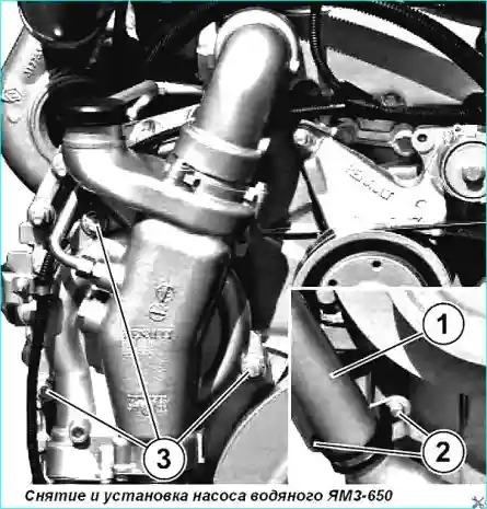
4. Remove the water pump gasket (650.1307048).
Disassembling the water pump (see Figure No. 2)
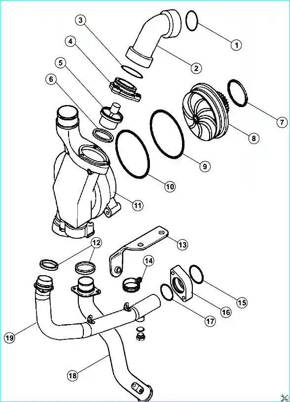
Expanded diagram of the water pump: 1 Sealing ring of the inlet pipe, 2 - Pipe supplying coolant from the cylinder head to the water pump, 3, 6, 9, 10, 15, 17 - Sealing rings, 4 - Coupling, 5 Thermostat (650.1306100), 7 - Water pump gasket (650.1307048), 8 - Bearing housing with axle, impeller and gear of water pump assembly (650.13070 13); 11 - Water pump housing; 12 - Sealing ring (650.1303018); 13 - Pipe mounting bracket 14 - Clamp: 16 - Flange of supply pipe (650.13031 68); 18 - Supply pipe of water pump assembly (650.1303060); 19 - Supply pipe of liquid-oil heat exchanger (650.1 303150).
- 1. Disconnect the supply pipe of water pump assembly (18).
- 2. Set aside sealing rings (12). (Fig. 2)
- 3. Remove the assembly (2 - 4) as a set.
- 4. Set aside the sealing ring (1).
- 5. Remove the assembly (8 - 11) as a set.
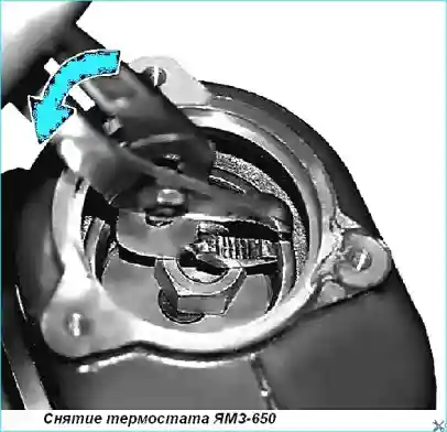
- 6. Remove the thermostat (5) (see Fig. 3).
- 7. Remove the sealing ring (6)
Checking the thermostat
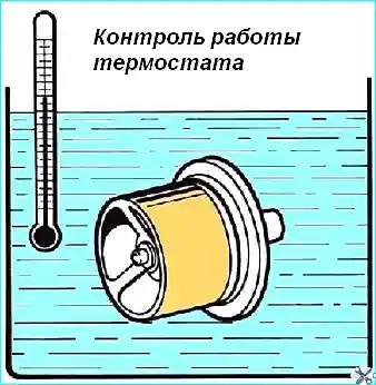
Dip the thermostat in a tank of water.
Heat slowly, stirring the water.
Check the opening temperature.
Check the thermostat opening at 90˚ C (see Fig. 4)
- 1. Wet the outer surface of the sealing rings (9, 10) with soapy water.
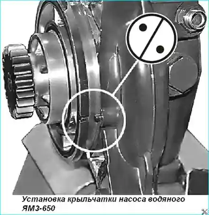
- 2. Install the bearing housing with the axle, impeller and gear of the water pump in assembly, observing the direction (see Fig. 5).
- 3. Install the thermostat (5).
Assembling the water pump
4. Install the assembly (2 - 4) as a set and tighten to the recommended torque (see Table).
Fastener tightening torques:
- Fan support mounting studs preliminary tightening torque: 50 ± 5 Nm, final tightening torque: 120 ± 12 Nm
- Coolant supply pipe plug to heat exchanger 40 ± 5 Nm
- Coolant pipe fitting nuts 25 ± 5 Nm
- Water pump mounting bolts 20 ± 4 Nm
- Fan belt tension roller mounting bolts 40 ± 8 Nm
- Coolant drain plug on heat exchanger tube 40 ± 5 Nm
- Water pump mounting studs 30 ± 6 Nm
Water pump installation
- 1. Install the gasket on the water pump.
- 2. Lubricate the mounting surfaces of the water pump necks.
- 3. Install the water pump on the front cover, engage the pump gear with the intermediate gear.
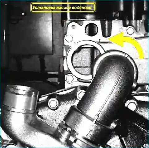
- 4. Rotate the pump around the axis so that the elbow pipe is located opposite the mounting neck of the coolant drain box from the cylinder head (see Fig. 6).
- 5. Install the branch pipe on the neck, moving the water pump to the cover, applying pressure at the level of the thermostat box.
- 6. Install 3 bolts in the pump mounting holes and screw into the cover. Install the wire bracket under one of the bolts.
- 7. Tighten the water pump mounting bolts to a torque of Mkr = 204 Nm.
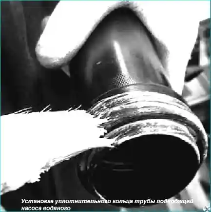
- 8. Install the sealing ring on the water pump inlet pipe. Apply grease with a brush to the sealing ring and into the water pump mounting hole (see Fig. 7)
- 9. Install the inlet pipe into the water pump hole, slightly turning it around the axis.
- 10. Screw in two pipe flange mounting bolts and tighten to a torque of Мкр = 204 Nm.
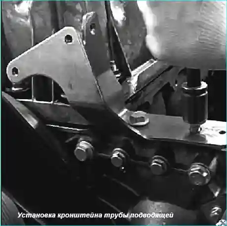
- 11. Install the bracket on the front cover (see Fig. 8), screw in 2 bolts and tighten to a torque of Мкр = 408 Nm.
- 12. Install the clamp, screw in 2 bolts for its mounting and tighten to a torque of Мкр = 408 Nm.


