Engine lubrication system (Fig. 1) mixed under pressure and splash
Main and connecting rod bearings, piston pins, camshaft bearings, bushings and rocker arms, pushrod bushings, pushrod tips, oil pump bearings and its drive are lubricated under pressure;
Cylinder liner mirrors, camshaft cams, unit drive gears and rolling bearings are lubricated by splash.
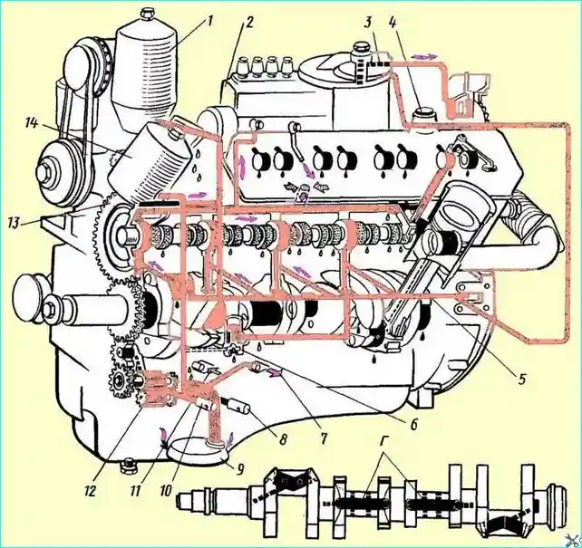
Fig. 1. Lubrication system diagram: 1 - centrifugal oil filter; 2 - high-pressure fuel pump; 3 - turbocharger oil filter; 4 - oil filler neck; 5 - central oil channel; 6 - differential valve; 7 - direction of oil flow to the oil radiator; 8 - radiator section safety valve; 9 - oil pump oil intake; 10 - pressure-reducing valve; 11 - direction of oil flow from the radiator to the sump; 12 - oil pump; 13 - oil filter bypass valve, 14 - coarse oil filter; (A) - high pressure; (B) - oil suction; (C) - drain and splash lubrication; (G) - crankshaft oil channels
Oil pump (Fig. 2).
Gear type, installed on the front cover of the main bearing and driven by the crankshaft gear through the intermediate gear; consists of two sections - main and radiator.
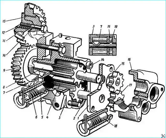
Fig. 2. Oil pump: 1 - pump section housing spacer; 2 - axle of driven gears of the main and radiator sections; 3 - pump main section housing; 4 - driven gear of the main section; 5 - pressure reducing valve; 6 - adjusting washer; 7 - main section drive gear; 8 - main and radiator section drive shaft; 9 - pump drive driven gear; 10 - intermediate gear axis; 11 - intermediate gear; 12 - thrust flange; 13 - sleeve; 14 - section housing mounting sleeve; 15 - radiator section driven gear; 16 - radiator section housing; 17 - radiator section driven gear; 18 - safety valve; 19 - locking ball
The main (discharge) section of the pump supplies oil to the main oil line through a series-connected coarse filter 14 (see Fig. 1).
A bypass valve 12 (Fig. 3) is installed in the coarse filter housing, which opens when the pressure difference before and after the filter is equal to 1.8-2.3 kgf/cm² (when the filter element is contaminated), and some of the uncleaned oil, bypassing the filter, enters the oil line.
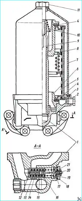
Fig. 3. Coarse oil filter: 1 - filter housing, 2 - drain plug; 3 - cap gasket; 4 - filter element gasket; 5 - filter element; 6 - lower cover of the filter element; 7 - filter cap: 8 - upper cover of the filter element; 9 - filter rod: 10 - spring; 11 - cap fastening bolt; 12 bypass valve; 13 - valve spring; 14 - alarm spring; 15 - alarm housing; 16 - movable contact; 17 - valve plug gasket; 18 - valve plug; 19 - valve spring adjusting washer; 20 - alarm terminal; 21 - fixed contact
By the time the bypass valve 12 starts to open, the contacts of the indicator will close:
- at this moment the signal lamp lights up in the cabinet.
After the filter, the oil enters the central oil channel, and from there through the channels in the cylinder block to the bearings of the crankshaft and camshafts.
From the crankshaft bearings, through a system of channels in the crankshaft and connecting rods, the oil is supplied to the bearings of the upper heads of the connecting rods.
From the camshaft, the oil is directed in a pulsating flow to the channel of the tappet axis and from there through the channels in the tappets, along the hollow rods and rocker arm holes - to all the rubbing pairs of the valve drive.
From the central oil channel through the outer wheelhouse, the oil goes to the bearings turbocharger through an additional fine filter (Fig. 4).
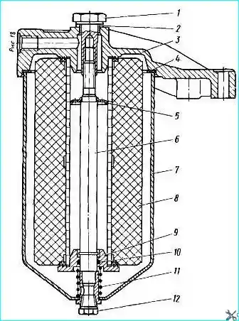
Fig. 4. Turbocharger oil filter: 1 - housing fastening bolt; 2 - gasket; 3 - filter cover; 4 - housing gasket; 5 - element retainer; 6 - rod; 7 - housing; 8 - filter element; 9 - sealing cup; 10
- sealing ring; 11 - spring; 12 - drain plug
After the coarse filter parallel to the main oil line, a centrifugal fine oil filter 1 (see Fig. 1) is connected, which passes up to 10% of the oil passing through the lubrication system.
The purified oil is drained into the sump.
The discharge section of the oil pump is equipped with a pressure-reducing valve 10 (see Fig. 1), which bypasses the oil into the sump when the pressure at the pump outlet is more than 7-8 kgf/cm².
A safety valve 8 is installed in the housing of the radiator section of the pump, adjusted to a pressure of 0.8-1.2 kgf/cm².
A differential valve 6 is included in the lubrication system to stabilize the pressure. It is adjusted to begin opening at 5.2 - 5.4 kgf/cm².
Fine oil filter
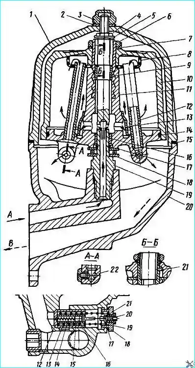
Fig. 5. Centrifugal oil filter: 1 - filter cap; 2 - washer; 3 - cap nut; 4 - rotor fastening nut; 5 - thrust washer; 6 - rotor nut; 7 - washer; 8 - mesh; 9, 16 - rotor bushings; 10 - rotor cap; 11 - rotor; 12 - intake tube; 13 - reflector; 14 - sealing ring; 15 - cap gasket; 17 - retaining ring; 18 - bearing; 19 - rotor axis; 20 - filter housing; 21 - pin; 22 - rotor nozzle
Centrifugal filter (centrifuge). The rotor 11 (Fig. 5) of the filter is driven into rotation by the reactive torque created by the oil flowing out of the nozzles 22 at a higher speed.
When the rotor rotates, the mechanical particles in the oil are thrown to the inner cavity of the cap 10, forming a dense sediment that is removed when the filter is disassembled.
The purified oil is drained into the engine crankcase.
Oil radiator
Tubular, air-cooled, located in front of the water-cooled radiator. It is turned on at an air temperature of 15 °C and higher, by opening the tap located on the left side of the cylinder block.
Under severe operating conditions, the oil radiator should be turned on at lower air temperatures. In all other cases, it must be switched off.
Possible malfunctions of the lubrication system and how to eliminate them
- Cause of malfunction - Method of elimination
Low oil pressure:
- - Insufficient amount of oil in the lubrication system - add oil
- - Oil dilution with fuel - Eliminate fuel leakage in the drain line under the cylinder head covers, in the threaded connections of the injectors and at the points where the fuel lines are connected to the injectors
- - Increased oil temperature - Malfunction of the oil cooling system
- - Contamination of the filter element of the coarse filter - Flush the filter element
- - Clogged oil pump intake - Flush the pump intake
- - Jamming of the plunger of the pressure reducing or drain oil pump valves - Flush without disassembling the valve
- - Wear of oil pump parts - Disassemble the oil pump and replace the manufactured parts, if necessary, replace
- - Wear of main and connecting rod bearings - Replace the liners
Low oil pressure in the turbocharger:
The oil pressure in the turbocharger will decrease simultaneously with the drop in oil pressure in the main line with any of the above-listed malfunctions of the lubrication system. In addition, the following may occur:
- - Breakdown of the oil supply pipe to the turbocharger - Replace or repair the pipe
- - Malfunction of the oil pressure gauge in the turbocharger lubrication system - Replace the pressure gauge. Change the turbocharger oil filter element with filter flushing
- - Turbocharger bearing wear - Remove the turbocharger from the engine and send it to a workshop for repair
Water gets into the lubrication system:
- - Cylinder head gaskets are damaged - Replace the faulty gasket
- - Injector cup nut is not tightened enough - Tighten the injector cup mounting nut
- - Cylinder liners are leaky - Replace faulty sealing rings
- - Crack in the cylinder head or block - send the engine for repair


