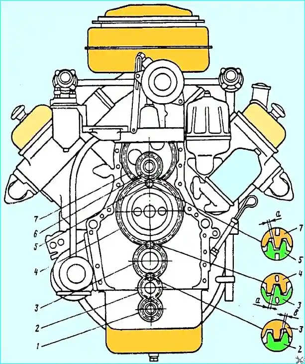
The arrangement of the engine mechanism drive gears subject to restoration or replacement during engine repair is shown in Fig. 1

Fig. 1. Gears: 1 - oil pump drive gears; 2 - oil pump intermediate drive gears; 3 - crankshaft gears; 4 - camshaft gears; 5 - fuel pump drive pinion; 6 - fan drive gear; 7 - driven gear of the fuel pump drive
The condition of the working surfaces of the gear teeth is checked by visual inspection.
Gears with contact destruction (pitting), wear in the form of grooves, chips, cracks, burrs and nicks are subject to replacement.
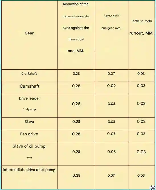
Gears with no defects are checked in backlash-free engagement with a control (standard) gear with a tooth thickness along the pitch circle arc of 3.927 mm for compliance with the permissible parameters (Table 1).
Since all gears are assembled in pairs and run-in, it is not recommended to disassemble them.
If, after checking for backlash-free engagement, some of them are rejected and the completeness is violated, the pair of gears must be assembled along the contact patch teeth.
The contact patch should be in the middle of the tooth and occupy an area of at least 40% of its length and 45% of its height, since the camshaft gear, intermediate gear of the oil pump drive and leading gear of the fuel pump drive have a barrel-shaped shape.

Fig. 2. Location of the contact patch on the gear teeth: (a) - correct; (b) - incorrect
In case of impersonal repair, when the completeness is violated, the engine gears must be checked for contact of teeth with the control gear.
Each set of control gears must include three gears adjusted to each other so that the contact patch of any of them with another, included in the set, covers 100% of the length 60% of the tooth height.
Of the three control gears that make up the set, only one is allowed to be used as the working one for checking the engine gears.
The working gear is checked periodically for the other two, and if the latter is worn out, a new control gear is made.
In this case, the contact patch of new engine gears in engagement with the control gear must be at least 80% in length and 55% in tooth height, and for used gears, at least 70% in length and 45% in height tooth.
It is permissible to reduce the tooth contact spot by height up to 30%, provided that it is located in the pitch circle zone.
For gears with barrel-shaped teeth, contact along the length is allowed up to 40%.
The correct contact position on the tooth surface of the new gear is shown in Fig. 2, a.
The presence of edge contacts on the tooth leg, bifurcated contact (Fig. 2, b) and wandering contact (Fig. 2, c) is not allowed.
Permissible parameters of engine gears


