The engine's power and economic performance, as well as its operational reliability, largely depend on the thoroughness and quality of the fuel injection pump adjustment.
Therefore, the adjustment must be performed by qualified personnel and on special equipment designed for these purposes.
It is recommended to adjust the fuel injection pump on the Star-12, Minor-8 (VNR), NC-108 and other stands similar in design.
The pump must be adjusted with a set of tested injectors assigned to the sections; the injectors must be installed on the engine in the order in which they are assigned to the pump sections.

When adjusting the fuel pump, first adjust the start of fuel supply by the pump sections, and then the amount and uniformity of fuel supply.
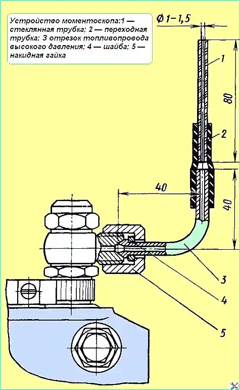
The start of fuel supply is adjusted without an automatic injection advance clutch by the start of fuel movement in the torque scope (Fig. 1).
The start of fuel supply by sections is determined by the angle of rotation of the pump camshaft when it rotates clockwise, when viewed from the drive side.
The first section of a correctly adjusted pump begins to supply fuel 37-38˚ before the axis of symmetry of the cam profile.
To determine the axis of symmetry of the cam profile, it is necessary to fix the moment of the start of fuel movement in the torque scope when the cam shaft is turned clockwise on the limb, turn the shaft clockwise by 90 ° and fix it on the limb the moment of the start of fuel movement in the torque scope when the shaft is turned counterclockwise.
The midpoint between the two fixed points determines the axis of symmetry of the cam profile.
If the angle at which the first section begins to supply fuel is conventionally taken as 0˚, then the remaining sections should begin to supply fuel in the following order:
Section - degree of rotation of the camshaft
- № 1 - 0˚
- № 3 - 45˚
- № 6 - 90˚
- № 2 - 135˚
- № 4 - 180˚
- № 5 - 225˚
- № 7 - 270˚
- № 8 - 315˚
The inaccuracy of the interval between the start of fuel supply of any section of the pump relative to the first is no more than 0˚20'.
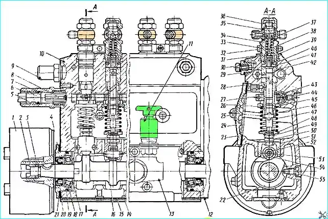
The start of fuel supply is adjusted by the pusher bolt 49 (see Fig. 2).
When the bolt is unscrewed, fuel begins to be supplied earlier, when screwed in, later.
After adjustment, it is necessary to lock the adjusting bolt with nuts.

The amount and uniformity of fuel supply by the high-pressure fuel pump sections are adjusted together with a set of injectors and high-pressure fuel lines 415 ± 3 mm long.
The volume of the internal cavity of each high-pressure fuel line should be 1.3 ± 0.1 cm³, it is determined by the fuel filling method.
The sequence of checking and adjusting the amount and uniformity of supply is as follows (the rotation speeds of the pump camshaft are indicated):
- check the fuel pressure in the line at the inlet to the high-pressure pump.
The pressure should be within 0.5 -1.0 kgf/cm² at 1050 min¹.
If the pressure is more or less, unscrew the bypass valve and adjust the opening pressure by turning its seat. After adjustment, calk the valve seat;
- when the control lever rests against the minimum speed limiting bolt, check and, if necessary, adjust the frequency of the full automatic shut-off of the feed by the regulator within 275 - 325 min¹.
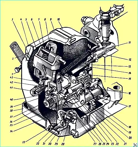
When unscrewing bolt 1 (see Fig. 3) of the minimum speed limiting bolt and the housing 41 of the buffer spring, the frequency decreases;
- when the control lever rests against the maximum speed limiting bolt, check the speed of the pump camshaft, corresponding to the start of rack ejection (the start of the rack movement towards shutting off the feed).
The regulator should start to eject the rack at 1070+10 min¹.
If necessary, adjust the frequency by the maximum speed limiting bolt;

- when the control lever rests against the maximum speed limiting bolt, check the speed of the pump camshaft corresponding to the end of the rack ejection (complete shutdown of the feed).
The end of the rack ejection should be at 1120 - 1150 min¹ .
In case of deviation from this value, unseal and remove the cover of the regulator inspection hatch.
When removing the cover, carefully ensure that the position of the adjusting screw remains unchanged.
The speed of rotation of the end of the rack ejection is adjusted as follows:
- by changing the position of screw 3 (see Fig. 3) of the double-arm lever, set the start of the rack ejection at 1070+10 min¹ with the maximum speed limiting bolt, check the speed of rotation of the end of the ejection racks in, if necessary, adjust it.
When screwing in the screw of the double-arm lever and setting the start of the rack ejection at 1070+10 min¹, the rotation speed of the end of the rack ejection decreases, when unscrewing it increases;
- when the control lever rests on the maximum speed limiting bolt and 1030±10 min¹, check the performance of the pump sections.
The fuel supply by each section of the pump when working with injectors having an "H" sprayer and adjusted to a pressure of 200+15 kgf/cm² at the beginning of the needle lift should be within 128-130 mm³ for each plunger stroke (cycle) for YaMZ-238PM engines and 138-140 mm per cycle for YaMZ-238FM engines.
The fuel supply by each section of the pump is regulated by shifting the rotary bushings relative to the gear ring, for which it is necessary to loosen the clamping screw of the corresponding gear sector.
When turning the bushing to the left relative to the ring, the feed decreases, to the right it increases.
After adjustment, check the reliability of tightening the clamping screws;
- check the value of the starting fuel supply, which should be within 220 - 250 mm³ per cycle at 80 ± 10 min¹ .
Make adjustments with screw 31 (see Fig. 3) of the linkage only in the direction of increasing the fuel supply, after which lock the screw with a coin.
After adjustment, check and, if necessary, adjust the performance of the pump sections with the nominal feed adjustment screw;
- check the shutdown of the fuel supply with the regulator bracket.
When turning the bracket to the lower position by 45, the fuel supply by all sections of the pump should be completely stop.
If the feed does not turn off, then you should check the ease of movement and eliminate possible jamming of the rack;
- - seal the high-pressure fuel pump and regulator;
- - install the automatic clutch and tighten its mounting nut with a torque of 10-12 kgcm.
The injection advance clutch mounting nut is tightened in all cases when the high-pressure fuel pump is removed from the engine.


