Installing the cylinder-piston group
Before installation, the liners must be matched to the cylinders and the amount of flange protrusion checked
We select the liners without rubber rings so that they fit into place with a slight pressure of the hand.
The lower end of the liners must fit precisely into the corresponding hole in the cylinder block.
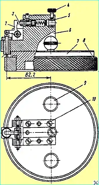
The protrusion of the liners flange above the plane of the cylinder block must be within 0.07 - 0.16 mm; it is checked with a device (Fig. 1).
To check the protrusion of the liners flange, the device with base 7 is installed on the liners. In this case, pin 1, moving upwards, will turn lever 2, which will move the indicator leg via rod 3.
The deviation of the indicator arrow from the zero reading will give the actual value of the liner flange protrusion.
There are two handles 9 for installing the device, which are secured with four screws 10 to body 6.
The indicator is installed in sleeve 5 and secured with screw 4.

Before using the device, it is necessary to adjust the indicator so that the arrow is opposite the number 0. The indicator is adjusted on the installation ring 8.
We remove the selected sleeve from the block cylinder, clean the seating and sealing surfaces and install rubber sealing rings lubricated with diesel oil in the grooves of the sleeve.
To seal the sleeves, use rings of the specified size only. They should create a good seal, but in no case should they be put on too tightly.
If rings are installed that are too tight and have a larger cross-sectional diameter than intended, the sleeve may be deformed, which will lead to piston seizure.
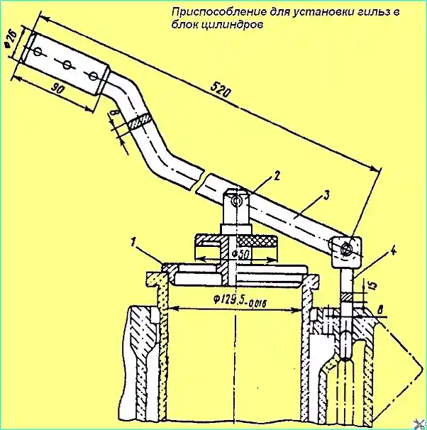
The sleeve assembly with sealing rings is installed in the cylinders using a device (Fig. 2).
To do this, hook 4 is installed on the jumper between the cooling jacket windows, and mandrel 1 in the sleeve, and through lever 3 and stop 2, we install the sleeve in the block cylinders so that the sleeve class marking is directed towards the front of the engine (towards the fan).
When installing the sleeves, care must be taken to ensure that the sealing rings do not twist.

To install the piston group, it is necessary to turn the cylinder block with the flywheel housing down, wipe and lubricate the inner surface of the cylinder liners, turn the crankshaft to a position convenient for assembly, and wipe the first connecting rod journal.
Then the piston assembly with the connecting rod and rings of the first cylinder, installed in the technological sleeve, is placed with the piston skirt in the sleeve of the first cylinder and the piston is pushed into the sleeve.
The piston of the fifth cylinder with the connecting rod and rings in assembly for the YaMZ-238 engine or the fourth - for the YaMZ-236 engine is installed in the corresponding cylinder.
We install the removed covers on the connecting rod journal of the crankshaft, screw in the bolts, with the lock washers, and tighten them finally with a torque of 160-180 Nm (16-18 kgfm).
Then we check the total clearance between the ends of the lower heads of the connecting rods and the cheeks of the crankshaft (axial clearance), which should be within 0.15-0.57 mm.
We take measurements between the ends of the connecting rods and their caps.
If the clearance is less than the specified one, it is necessary to loosen the tightening of the bolts and lightly hit the connecting rod cap with a rubber hammer to move it until the required clearance is obtained.
After adjustment, bend the whiskers of the lock washers on the edge of the heads of the connecting rod bolts.
In the same sequence, we install the remaining pistons in pairs with connecting rods and rings in the assembly, according to the numbering of the cylinders: for engine YaMZ-238: 2-6, 3-7, 5-8 and for the YaMZ-236 engine - 2-5,3-6.

After installing the connecting rod and piston group, the crankshaft should rotate smoothly by hand using a lever with a shoulder of 550 mm without jamming.
When installing the piston group, the following conditions must be observed.
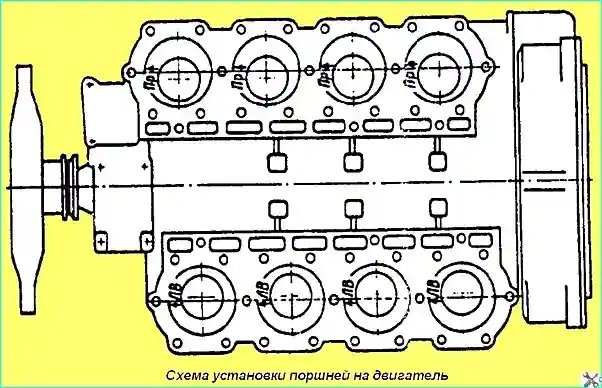
The arrow on the piston bottom, as well as the lug on the piston pin boss, must point towards the front part towards the fan.
Sme the chamber in the piston should be directed towards the engine axis (Fig. 3).
For the right row of cylinders, pistons with the "PR" sign on the bottom are installed, for the left row of cylinders - the "LV" sign.
Installing the oil pump and cylinder block sump
If there are no studs for fastening the oil pump, screw them into the cover of the front crankshaft bearing until they stop with a torque of less than 30 Nm (3 kgm).
Then install the gaskets of the flange of the oil line outlet pipes and the adjusting gaskets of the oil pump housing on the block.
We install the oil pump assembly on the studs and secure it with two nuts with engraving washers. In this case, the clearance in the engagement of the crankshaft gear with the intermediate gear of the oil pump must be within 0.25 - 0.37 mm.
Check the clearance with a set of feeler gauges at least in three points.
If the clearance is not within the tolerance, then it is necessary to loosen the oil pump mounting nuts and install the required number of adjusting shims, which should not exceed three pieces, between the pump body and the crankshaft main bearing cover.
After adjusting the clearance, fasten the oil pump outlet oil lines on the cylinder block and pump body and the bracket of the suction oil line with bolts with lock washers placed underneath.
When checking the mating plane of the flanges of the oil outlet line 08 and the flange of the suction oil line, a feeler gauge with a thickness of 0.05 mm should not pass. The whiskers of the lock washers must be bent at the edges of the bolts and nuts.
Screw the drain valve of the lubrication system into the cylinder block assembled with the lock washer and tighten it to the limit, and then bend the edges of the washer onto the valve body and the cylinder block.
To install the pan on the crankcase, screw two guide pins into the holes for the pan mounting bolts.
Put the gasket on the pins, the pan, and screw the bolts with the spring washers into the aligned holes.
Before installing the pan, make sure there are no foreign objects in it and blow it out with compressed air.
Screw two drain plugs with copper gaskets into the pan to the limit.
In the next post we will consider:
- - installing the heads cylinders, rocker arms and valve clearance adjustment;
- - installation of injectors, fuel lines;
- - Running-in and running-in of diesel.


