Disassembling and checking the pump
Before disassembling, the pump must be removed from the car, after draining the oil from the pump and cleaning and washing its outer surface
The procedure for disassembling and checking the pump:
Remove the tank cover and filters.
Remove the tank by unscrewing the four bolts.
Install the pump so that its shaft is vertical and the pulley is at the bottom, and remove the pump cover by unscrewing the four bolts.
When removing the cover, hold the valve from falling out
Mark the position of the distribution disk relative to the stator and remove it from the pins.
Mark the position of the stator relative to the pump body and remove the stator (the arrow on the stator indicates the direction of rotation of the pump shaft).
Remove the rotor together with blades.
The stator, rotor and blades of the pump are individually selected at the factory, so their completeness cannot be violated during disassembly. It is also forbidden to swap the blades.
When replacing the stator, rotor and blades, install them only as a set.
In case of emergency, remove the pulley, retaining ring and pump shaft together with the front bearing.
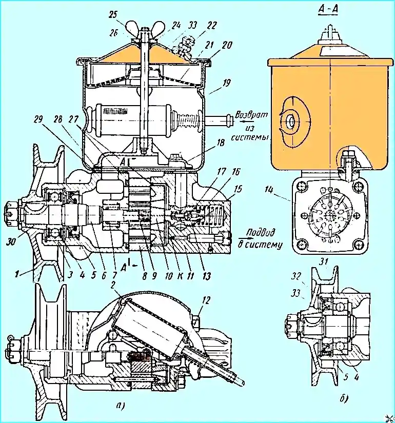
Fig. 1. Power steering pump: (a) - pump before modification; (b) - pump shaft end after modification; 1 - pulley; 2 - mesh filter; 3 - pump housing; 4 - front bearing; 5 - oil seal; 6 - pump shaft; 7 - rear bearing; 8 - stator; 9 - rotor; 10 - distribution disk; 11 - pump cover; 12 - filter bypass valve; 13 - bypass valve; 14 - blade; 15 - adjusting linings; 16 - relief valve seat; 17 - relief valve; 18 - manifold; 19 - reservoir; 20 - pump cover gasket; 21 - filler mesh filter; 22 - breather; 23 - reservoir cover; 24 - washer; 25 - wing nut; 26 and 27 sealing rings; 28 - manifold gasket; 29 - tank sealing gasket; 30 - conical bushing; 31 - bearing retaining ring; 32 - oil seal retaining ring; 33 - oil seal bushing; K - calibrated hole
If there is a large bearing (see Fig. 1, b), remove it only if necessary, since this may damage the seal and it will need to be replaced.
When installing a new bearing and seal, take measures to prevent damage to the edges of the seal.
Check the free movement of the bypass valve in the pump cover and the absence of nicks or wear.
The valve and pump cover are individually selected at the factory, so their completeness must not be violated during disassembly
If necessary, clean the nicks or replace the parts as a set.
Check the tightness of seat 16 (Fig. 1) of the safety valve and, if necessary, tighten it.
Check that there is no dirt in all the channels of the pump parts and clean them channels.
Check the end surfaces of the rotor, housing and distribution disk for scoring or wear.
In case of minor scoring or wear, lap these surfaces on a plate, then rinse the parts thoroughly.
Check whether the blades move freely in the rotor slots and whether they are excessively worn.
Assembling the pump
- 1. Assemble in the reverse order.
- 2. Install the stator-rotor with blades and the distribution disk in accordance with the marks made during disassembly and the arrow indicating the direction of rotation. In this case, the chamfer of the splined hole should face the pump body.
- 3. Install the cover with the bypass valve. The hexagon of the valve seat should face the inside of the hole.
- 4. The tightening torque of the M6 bolts securing the tank should be 0.6-0.8 kgm.
- 5. The tightening torque of the nut securing the pump pulley should be 5.0-6.5 kgm.
- 6. The pump shaft must rotate freely, without jamming.
Checking the pressure developed by the pump
The check must be carried out by installing a special device (Fig. 2) between the pump and the high-pressure hose, which has a pressure gauge with a scale of up to 80 kg/cm 2 and a valve that closes the oil supply to the power steering.
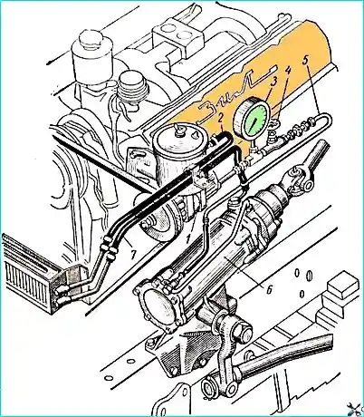
To check, open the valve and turn it to wheels to the stop; the oil pressure at low engine idle speed should be no less than 60 kg/cm 2.
If the oil pressure is less than 60 kg/cm 2, then you need to slowly tighten the valve, monitoring the increase in pressure on the pressure gauge.
If the pump is in good working order, the pressure should rise and be no less than 65 kg/cm 2.
In this case, the fault should be looked for in the steering mechanism. If the pressure does not increase, the pump is faulty.
If the pressure with the valve closed is greater than the pressure with the valve open, but lower than 60 kg/cm 2 , then both units are faulty.
When checking, do not keep the valve closed for more than 15 seconds, and the wheels turned to the stop.
The check must be carried out when the oil temperature in the tank is 65-75° C.
If necessary, the oil can be heated by turning the wheels from stop to stop, holding them at the stops each time for no more than 15 seconds.