The engine lubrication system is mixed.
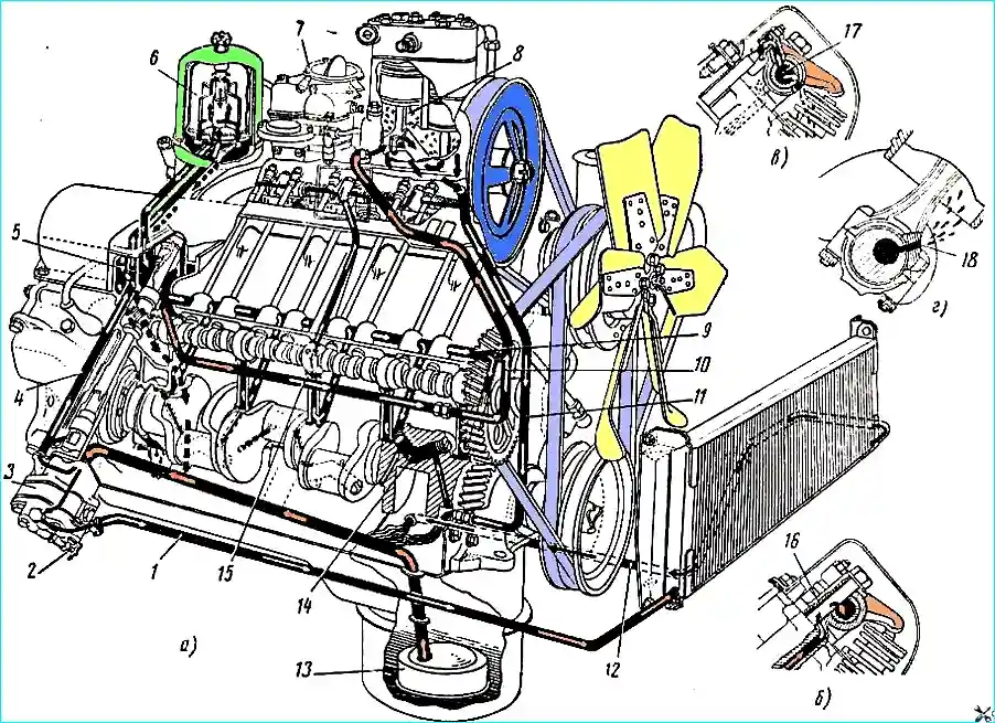
The lubrication diagram is shown in Fig. 1
Oil under pressure is supplied to the main and connecting rod bearings of the crankshaft, to the camshaft bearings, to the supports of the intermediate shaft of the ignition distributor drive and the oil pump shaft and to the tappets
A pulsating oil supply is provided to the rocker arm bushings.
Oil is supplied to the other rubbing parts of the engine by gravity and splashing.
From the oil sump, oil is sucked through a stationary oil receiver into the oil pump.
Through a channel in the rear bulkhead of the block, the pump delivers oil under pressure to the oil filter housing.
The oil, cleaned in the centrifugal filter, enters the distribution chamber located in the rear bulkhead of the block.
From the distribution chamber, the oil enters two longitudinal main channels; from the left channel, oil is supplied to the main bearings of the crankshaft, and from them to the bearings of the camshaft.
The channels in the crankshaft supply oil to the connecting rod bearings
A special hole is provided in the body of the connecting rod, when it coincides with the channel in the crankshaft journal, oil is sprayed onto the cylinder wall (Fig. 1, г).
The oil removed from the cylinder walls by the oil scraper ring is diverted through the holes in the groove of the ring into the piston and lubricates the bearings of the piston pin in the piston bosses and in the upper head of the connecting rod.
From the front end of the right (in the direction of the car) main channel, oil is supplied to lubricate the compressor.
There are two connecting holes in the middle journal of the camshaft, when they coincide with the holes in the block (once - with each revolution of the camshaft), oil is supplied to the channels made in each cylinder head.
From these channels, through a groove in the supporting surface of the rocker arm axle stand and a gap between the walls of the hole in the stand and the bolt passing through the stand, oil enters the hollow rocker arm axle, from where the oil enters the rocker arm bushings through holes in the wall of the axle (Fig. 1, б).
From the gap between the rocker arm axis and the hole in the rocker arm, oil is supplied through a channel made in the short arm of the rocker arm to lubricate the spherical bearings of the rods, as well as to lubricate the valves and valve rotation mechanisms, to which the oil flows by gravity (Fig. 1, б).
The rod pushers are lubricated with oil from the longitudinal main channels.
Crankcase ventilation is forced, by sucking crankcase gases into the engine intake manifold through a special valve 3 installed on the intake manifold.
From the valve, gases are sucked through a special tube into the central part of the intake manifold.
Tap 4 is installed between the tubes to turn off the ventilation system when fording.
The tap handle must be positioned vertically when fording. After crossing the ford, the handle must be turned to the horizontal position.
When the engine is running with the throttle valve slightly open, under the action of a large vacuum in the intake manifold, valve 3 rises, the upper stepped part of the valve enters the hole of the fitting 5 and reduces the flow area of the valve to the value necessary for the passage of a small volume of gases breaking through into the engine crankcase.
When the engine is running with the throttle valve fully open, the vacuum in the intake manifold drops and the valve, under the action of its own weight, drops, completely opening the flow area, the value of which corresponds to the passage of a large volume of gases breaking through into the engine crankcase.
At the times specified in the "Vehicle Maintenance" section, it is necessary to clean the valve using acetone or another similar solvent.
Oil Radiator tubular air-cooled, installed in front of the main radiator of the engine cooling system.
The oil radiator must be constantly on, and it should be switched off only when starting a cold engine at an outside temperature below 0° C.
At low temperatures in winter, the oil radiator can also be switched off. The oil radiator is switched off by valve 2 (see Fig. 1).
During all engine maintenance work, it is necessary to remember that the engine is designed to operate when immersed in water; therefore, all joints between units, regardless of the presence of gaskets in them, are sealed with sealant.