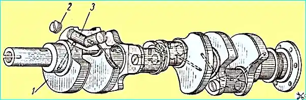
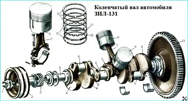
The crankshaft is steel, with hardened journals, five-bearing, with channels for lubrication and centrifugal traps for cleaning oil, the diameter of the main journal is 75-0.020 mm, and the connecting rod is 65.5-0.020 mm (Fig. 1)
The main bearing shells are thin-walled trimetallic, 2.25-0.013 mm thick, interchangeable on each support (except the rear).
In a new engine, the diametrical clearance in the connection of the crankshaft main journal - the block with the bearing assemblies is 0.026-0.085 mm.
The main bearing cap bolts must be tightened with a torque wrench. The tightening torque should be 11-13 kgm.
Check and tighten the main bearing cap bolts, if necessary, each time the oil pan is removed.
In a new engine, the axial clearance of the crankshaft in the thrust bearings is 0.075-0.245 mm.
When the connecting rod or main bearings are worn, both halves of the bearings must be replaced simultaneously.
The crankshaft is dynamically balanced in assembly with the flywheel and clutch.
The torque of fastening the flywheel bolts to the crankshaft flange should be 14-15 kgm.
To prevent oil leakage, a rubber frame seal is installed on the front end of the crankshaft.
For the same purpose, at the rear end of the crankshaft there is a drainage groove in the rear main bearing shell (with a hole for draining oil), an oil drain ridge, an oil-scraping spiral groove, an asbestos packing seal, an oil-scraping spiral knurling on the crankshaft journal under the packing and rubber seals under the main bearing cap.
The cast iron flywheel, with a steel toothed ring for starting the engine from the starter, is attached to the flange of the rear end of the crankshaft with six bolts.
When removing the flywheel, to facilitate subsequent assembly, it is necessary to mark its installation on the crankshaft, since the flange crankshaft has offset (asymmetrical) holes.
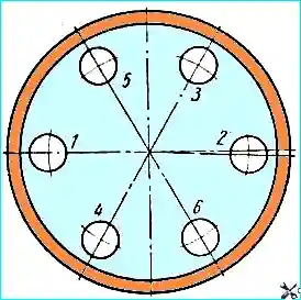
When securing the flywheel to the crankshaft flange, tighten the nuts evenly in the order shown in Fig. 2.
It is necessary to ensure that the flywheel mounting bolts are carefully cotter-pinned. The cotter pin must fit tightly around the end of the bolt.
When installing the flywheel, it is necessary to check the runout of its working surface (the mating surface with the driven clutch disk)
in relation to the crankshaft axis. At a radius of 150 mm, this runout should be no more than 0.15 mm.
Note: Since October 1969, engines have been manufactured with bimetallic liners 2.5-0.025 mm thick and with a crankshaft with main journals 74.5-0.020 mm in diameter.
The diametrical clearance in the main journal - block with liners in a new engine is 0.050-0.107 mm. The crankshaft complete with liners is interchangeable.