Engine 3IL-131 V-shaped, eight-cylinder, four-stroke, carburetor, with liquid cooling
The engine is attached to the frame at three points.
The front engine support is a bracket installed under the timing gear cover; The rear supports are the clutch housing legs.
Round rubber cushions are installed between the bracket and the front cross member of the frame, as well as between the clutch housing legs and the rear engine mounting brackets.

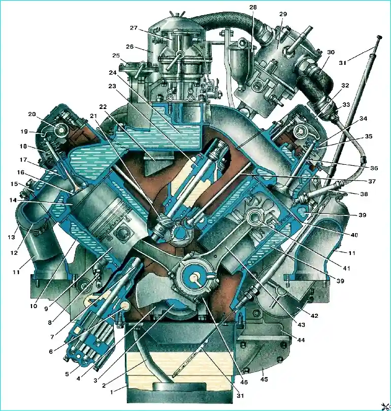
Longitudinal section of the engine 3IL-5081.10: 1 - crankshaft pulley; 2 - ratchet; 3 - cylinder block; 4 - ignition timing indicator; 5 - speed limiter sensor; 6 - limiter sensor drive shaft; 7 - shaft pressure spring; 8 - spacer ring; 9 thrust flange; 10 camshaft drive timing gear cover; 11 - liquid pump; 12 - liquid pump pulley; 13 - alternator drive belt; 14 - power steering pump drive belt; 15 - compressor drive belt; 16 - plug; 17 - oil can; 18 - eye bolt; 19 crankcase ventilation pipe and oil filler neck; 20 - fuel pump; 21 - fuel pump rod; 22 fine fuel filter; 23 - ventilation system valve tube; 24 centrifugal oil filter (centrifuge); 25 - engine cooling system temperature gauge sensor; 26 - camshaft; 27 - main bearing shell; 28 - rear main bearing seal; 29 clutch housing; 30 - crankshaft; 31 - thrust washer; 32 - camshaft drive gear
The front and rear suspension cushions are interchangeable.
In addition, the engine is connected to the front cross member of the frame using a jet rod with rubber shock absorbers.
The jet rod is designed to keep the engine from longitudinal movement when the clutch is disengaged, the transfer case is engaged, or when the car is braking.
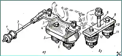
The engine mount is shown in Fig. 4
At the intervals specified in the "Vehicle Maintenance" section, it is necessary to check the tightening of the nuts of the front and rear engine mount bolts, as well as check the fastening of the jet rod.
The tightening torque of the nuts of bolts 8 of the rear suspension should be equal to 20-25 kgm, and the nuts of bolts 4 and 12 of the front and rear suspensions, respectively, 8-10 kgm.