The vehicle is equipped with power steering, which is combined into a single unit with the steering gear
Power steering reduces the effort required to turn the steering wheel to turn the front wheels, softens impacts caused by uneven road surfaces, and improves driving safety by allowing you to maintain control over the direction of the vehicle in the event of a front tire blowout.
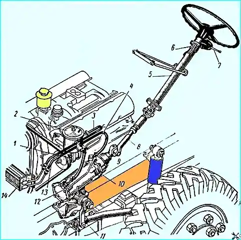
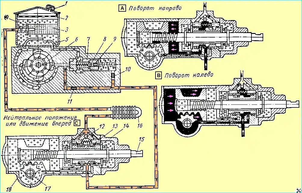
The diagram of the power steering is shown in Fig. 2.
The steering gear (Fig. 3) has a screw with a nut on circulating balls and a rack with a toothed sector. The steering gear ratio is 20: 1.
The steering gear is attached to the frame and connected to the steering column shaft by a cardan shaft with two joints.
The steering gear housing 4 is also the hydraulic booster cylinder in which the piston-rack 5 moves.
The plug 3 is rolled into the piston-rack.
The piston-rack engages with the toothed sector of the shaft 31 of the steering knuckle.
The teeth of the rack and the knuckle shaft have a variable thickness along the length, which allows adjusting the engagement gap by axially shifting the knuckle shaft.
The steering knuckle shaft rotates in bronze bushings 33, pressed into the housing and into the hole in the side cover 24 crankcase.
The axial position of the bipod shaft is determined by the adjusting screw 30, the head of which enters the hole in the bipod shaft and rests on the thrust washer 26.
The axial movement of the adjusting screw in the bipod shaft, maintained during assembly within 0.02-0.08 mm, is limited by the adjusting washer 27 and the locking ring 28.
The piston rack contains a ball nut 8, reinforced with set screws 42, which are punched after assembly.
The nut is preliminarily assembled with the screw 7 in such a way that 31 ball 10 is inserted into the screw grooves and groove available to them.
Two stamped grooves 9 are inserted into the groove of the ball nut, connected by two holes to its screw groove, forming a tube along which the balls, rolling out when the screw is turned from one end of the nut, return to its other end.
Screw 7 passes through intermediate cover 12, to which body 17 of the control valve is attached.
Two thrust ball bearings 13 with a spool 16 of the control valve between them are mounted on the screw.
Large rings of the ball bearings face the spool.
The ball bearings and the spool are secured with nut 19, the thinned flange of which is pressed into the groove on the screw.
A conical spring washer 18 is placed under the nut, ensuring uniform compression of the thrust ball bearings.
The spring is installed with the concave side facing the ball bearing.
The length of the spool is greater than the length of the hole for it in the body control valve. As a result, the spool and screw can move axially by 1.1 mm in each direction from the middle position.
They return to the middle position under the action of six springs 39 and reaction plungers 40, which are under oil pressure in the supply line from the pump.
Screw 7 rotates in needle bearing 21, located in the upper cover 20 of the steering gear.
Two hoses from the power steering pump are connected to the control valve body: high-pressure hose 4 (see Fig. 1), through which oil is supplied from pump 1, and low-pressure hose 3 (drain), through which oil returns to the pump.
When screw 7 (Fig. 3) rotates in one direction or another, due to the resistance arising when turning the wheels, a force is created that tends to shift it in the axial direction in the corresponding direction.
If this force exceeds the preliminary compression force of springs 39, then the screw moves and displaces spool valve 16. In this case, one cavity of the hydraulic booster cylinder communicates with the pressure line, and the other with the drain.
The oil coming from the pump into the cylinder presses on the piston rack, creating additional force on the sector of the steering knuckle shaft, and facilitates the turning of the wheels.
The pressure in the working cavity of the cylinder increases with increasing resistance to turning the wheels.
At the same time, the pressure under the jet plungers 40.
The screw and the spool tend to return to the middle position under the action of springs 39 and reaction plungers.
The greater the resistance to turning the wheels and the higher the pressure in the working chamber of the cylinder, the greater the force with which the spool tends to return to the middle position and set the thrust ball bearings and the screw to the middle position, the greater the force on the steering wheel.
When the force on the steering wheel increases with increasing resistance to turning the wheels, the driver gets a "feeling of the road".
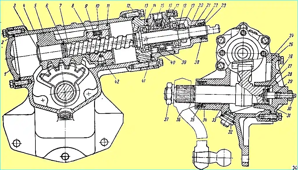
Steering gear: 1 - lower cover; 2, 14, 25, 29 and 41 - sealing rings; 3 - plug; 4 - steering gear housing; 5 - rack-and-pinion piston; 6 - split sealing ring; 7 - steering screw; 8 - ball nut; 9 - groove; 10 - ball; 11 - split piston rings; 12 - intermediate cover; 13 - thrust ball bearing; 15 - ball valve; 15 - spool valve; 17 - control valve housing; 18 - spring washer; 19 - adjusting nut; 20 - upper cover; 21 - needle bearing 22 and 35 - oil seal thrust rings; 23 - outer sealing cuff; 24 - side cover; 26 - thrust washer; 27 - adjusting washer; 28 - retaining ring; 30 - adjusting screw; 31 - pitman arm shaft; 32 - drain plug with magnet; 33 - pitman arm shaft bushings; 34 and 38 - oil seals; 36 - rubber cuff; 37 - pitman arm shaft nut; 39 - reaction spring; 40 - reaction plunger; 42 - adjusting screw
The force on the steering wheel rim, corresponding to the start of the hydraulic booster, is about 2 kg, and the greatest force is about 10 kg.
When the steering wheel stops turning, the oil entering the cylinder acts on the piston-rack with the screw, shifts the spool to the middle position, which causes a decrease in pressure in the cylinder to the level necessary to hold the wheels in the turned position, and stops the piston movement, and therefore the rotation of the wheels.
In the control valve body there is a ball valve 15, which connects the high-pressure and drain lines when the pump is not working.
In this case, the valve ensures the operation of the steering gear as a conventional steering gear without a hydraulic booster.
The cavity in which the thrust ball bearings are located is connected to the drain and sealed with rubber rings 14 round cross-section.
Similar rings 2, 25 and 41 also seal the other fixed joints.
Steering knuckle shaft 31 is sealed with rubber seal 34, which has thrust ring 35, preventing it from turning out under pressure.
Outer rubber cuff 36 prevents dirt and dust from getting onto the shaft.
The piston-rack is sealed with two cast-iron elastic split rings 11
Steering gear screw 7 has two seals in the intermediate cover and in the piston-rack. Sealing is performed by cast iron elastic split rings 6.
In the upper cover 20, the screw is sealed by a rubber seal 38 with a thrust ring 22 and an outer cuff 23.
The adjusting screw 30 is sealed by a rubber ring 29 of circular cross-section.
When the steering screw 7 is rotated in one direction or another from the middle position, the free play in the steering mechanism increases, as a result of which the width of the depression between the teeth of the piston-rack 5, which is in engagement with the middle tooth of the sector of the shaft 31 of the pitman arm, is reduced in comparison with the width of the remaining depressions, and the steering screw 7 has a barrel-shaped form with a slight decrease in the diameter of the screw groove towards its ends.
In the steering housing there is a plug 32 with a magnet, which catches steel and cast iron particles from oils.
The screw 7 of the steering control is connected to the steering column control of the cardan shaft.