The combined brake valve consists of two sections combined in one housing and is designed to control the pneumatic drive of the brakes of the tractor and trailer (semi-trailer)
The mechanical drive of both sections is carried out by a pair of levers.
The lower section controls the brakes of the tractor, and the upper section controls the brakes of the trailer or semi-trailer.
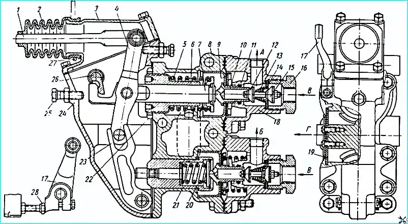
Both sections have unified valves and diaphragm follower mechanisms.
Two double conical valves together with inlet seats and return springs 13 are installed in covers 18 of the valve.
Two follower diaphragms 9 together with guide cups and seats 10 of the outlet valves are clamped between the body 8 of the valve and covers 18.
Each section has a balancing spring that provides a follower, i.e. a proportional dependence of the pressure of compressed air supplied by the brake valve on the force applied to the drive lever of the valve.
The balancing spring 5 of the trailer section is mounted on the rod 7; its preliminary tension is adjusted by moving the guide 6 of the rod.
The balancing spring 20 of the tractor section is mounted in the cup 21; its preload is adjusted by spacers.
Using lever 17, connected to the handbrake drive, it is possible to activate only the trailer section, followed by braking the vehicle with the handbrake.
The operation of the combination valve is as follows
When filling the pneumatic system with compressed air, the latter, with the outlet valve 12 closed, enters the trailer connecting line through the open inlet valve 15 of the trailer section.
When the specified pressure is reached, spring 5 is compressed and inlet valve 15 closes the trailer line.
After that, both valves of the trailer section and the outlet valve of the tractor section remain closed.
During braking, the force from the pedal is transmitted to drive lever 4; first, the exhaust valve 12 of the trailer section opens, and the compressed air from the trailer line is released into the atmosphere.
Then the exhaust valve closes and the inlet valve of the tractor section opens, and the compressed air enters the brake chambers of the tractor.
When braking, the load is removed from the drive lever 4, the exhaust valve closes, the inlet valve of the trailer section opens, and the compressed air from the air cylinders enters the trailer line; at the same time, the inlet valve closes, the outlet valve of the tractor section opens, and compressed air from the brake chambers of the tractor is released into the atmosphere.
Maintenance of the brake valve consists of periodic inspection, checking for leaks, checking the operation of the valve and cleaning it from dirt.
It is necessary to monitor the condition of the protective rubber boot and the tightness of the fastening of the covers to the body, since dirt getting inside the valve on the rubbing surfaces can lead to its failure.
It is also necessary to carefully monitor the cleaning of air in the brake system from water vapor and oil, since oil getting on the rubber parts of the brake valve can put them out of order.
During TO-2, it is necessary to check the tightness of the brake valve using a soap emulsion.
Air leakage through the outlet hole in the unbraked position indicates a leak the exhaust valve of the section that controls the trailer brakes, or the inlet valve of the section that controls the vehicle brakes.
When braking, air should come out of the trailer line through the exhaust port; if air continues to come out 1-2 seconds after pressing the pedal, this indicates that the inlet valve of the section that controls the trailer brakes, or the exhaust valve of the section that controls the vehicle brakes, is leaky.
If after two or three repeated brakings the air leak continues, the specified valves should be removed and inspected.
After 50,000-70,000 km of running, the brake valve should be removed, disassembled, the rubbing surfaces should be washed with clean kerosene, wiped with a soft cloth and lubricated with a thin layer of grease 158 according to MRTU 12N 3 139-64.
TsIATIM-201 grease can be used as a substitute. In this case, lubrication should be performed after 20,000-25,000 km of mileage, but not less than once a year.
Then reassemble the brake valve, having first checked the ease of movement of the diaphragm guide cups, cup rod, balance spring and levers.
After assembly, using the guide 6 of the rod (Fig. 1), it is necessary to adjust the air pressure in the section controlling the trailer brakes in the unbraked state within 4.8-5.3 kg / cm 2 (when screwing in the guide, the pressure increases).
After adjusting the pressure, the position of the rod guide must be fixed with lock nut 22.
Disassembly, cleaning and adjustment of the brake valve must be performed by a qualified mechanic and only in a workshop.
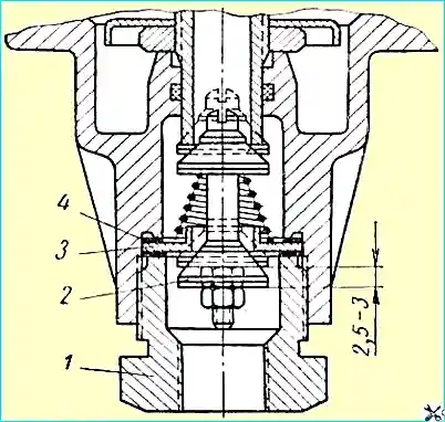
When installing conical valves, check and, if necessary, adjust the opening of the inlet valve using shims 4 (Fig. 2).
With the brake valve lever fully extended, the inlet valve stroke should be 2.5-3.0 mm.
The opening of the inlet valve can be measured as follows:
- - disconnect the pipe supplying air from the air cylinder to the brake valve, unscrew the connecting fittings from plug 1,
- - press the brake pedal all the way or pull lever 4 (see Fig. 1) of the brake valve (if the brake valve has been removed from the vehicle),
- - and then use a ruler or depth gauge through the hole in plug 1 (Fig. 2) to measure the inlet stroke valve.
Air leakage along the plane of the joint of the brake valve body and its covers indicates damage to the diaphragm or a leak in the valve parts at the point where they are connected to the diaphragm.
A damaged diaphragm should be replaced.