The compressor is a piston type, non-straight-through, two-cylinder, single-stage compression
Aluminum pistons, with floating pins; the pins in the piston bosses are secured from axial movement by retaining rings
Air from the engine air filter enters the compressor cylinders through self-acting plate inlet valves 21.
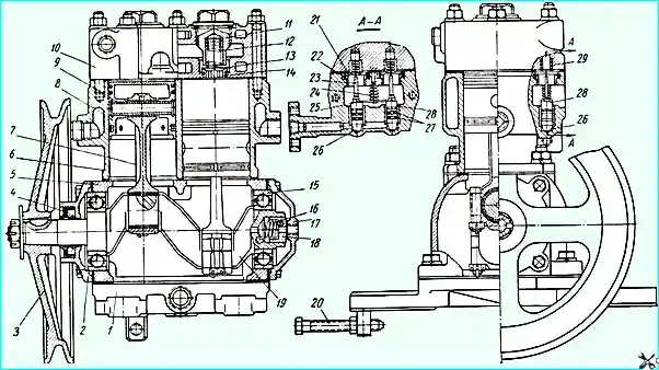
Air compressor: 1 - lower crankcase cover; 2 - front crankcase cover; 3 - pulley; 4 - crankshaft oil seal; 5 - compressor housing; 6 - cylinder block; 7 - connecting rod; 8 - piston with rings; 9 - piston pin with retaining rings; 10 - cylinder head; 11 - discharge valve plug; 12 - discharge valve spring; 13 - discharge valve; 14 - discharge valve seat; 15 - crankshaft rear bearing; 16 - seal spring; 17 - rear crankcase cover; 18 - seal; 19 - crankshaft; 20 - adjusting bolt; 21 - inlet valve; 22 - inlet valve guide; 23 - inlet valve stem; 24 - rocker arm guide spring; 25 - rocker arm; 26 - plunger; 27 - sealing rings; 28 - inlet valve stem seat; 29 - inlet valve spring
The air compressed by the pistons is forced into the pneumatic system through the self-acting plate discharge valves 13 located in the cylinder head.
The block and head are cooled by liquid supplied from the engine cooling system.
Liquid is supplied to the compressor cooling system from the water jacket of the engine intake pipe and drains from the head into the suction cavity of the water pump.
It should be borne in mind that the compressor cooling system is filled only when the engine is running.
Therefore, after pouring liquid into the radiator, you need to start the engine, let it run for 3-5 minutes and then check the level in the radiator.
The compressor shuts off the air supply to the pneumatic system as follows.
When the pneumatic air pressure system 7.0-7.4 kg/cm 2 the pressure regulator supplies compressed air through channel "A" in the cylinder block under the plungers 26 of the unloading device, which, rising, open the inlet valves 21 of the two cylinders, thereby stopping the air supply to the pneumatic system, since air is able to freely pass from cylinder to cylinder.
When the air pressure in the pneumatic system drops to 5.6-6.0 kg/cm 2, the regulator stops supplying compressed air under the plungers of the unloading device.
Air from under the plunger is released into the atmosphere; the plungers are lowered by the rocker spring, releasing the inlet valves, and the compressor begins to pump air into the pneumatic system again.
Oil is supplied to the rubbing surfaces of the compressor through a tube from the engine oil line to the rear cover of the compressor crankcase, and through the seal through the crankshaft channels to the connecting rod bearings.
The main ball bearings, piston pins and cylinder walls are lubricated by splashing.
The pulley is made of cast iron.
Compressor maintenance
It is necessary to periodically check the tension of the nuts, the fastening of the compressor on the engine head, the fastening of the pulley, the tension of the drive belt, the tightening of the nuts of the studs fastening the head.
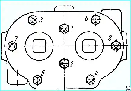
The order of tightening the nuts of the compressor cylinder head
The nuts of the studs securing the head should be tightened evenly, in two steps, in the order shown in Fig. 2.
The final tension torque should be within 1.2-1.7 kg/m after 80,000-100,000 km of run, combined with seasonal maintenance (in spring), it is necessary to remove the compressor head to clean the pistons, valves, seats, springs, air ducts, as well as to check the operation and tightness of the valves and plungers of the unloading device.
Valves that do not provide tightness must be ground to the seats, and heavily worn or damaged ones must be replaced with new ones.
New valves should also be ground to the seats until continuous ring contact is obtained when checking "for paint".
It is necessary to check the condition of the sealing rings of the plungers 26 (Fig. 1) of the unloading device and, if necessary, replace the rings.
In this case, the following must be observed order:
- 1. Start the engine and bring the pressure in the pneumatic system to 7.0-7.4 kg/cm 2.
- 2. Stop the engine.
- 3. Remove the rubber hose connecting the engine air filter to the compressor.
If the unloading device is not tight, a characteristic noise of air flowing through the air supply pipe to the compressor will be heard, and a slight pressure drop will be noted on the pressure gauge of the pneumatic system.
- 4. Reduce the air pressure in the pneumatic system to 5.6-6.0 kg/cm 2 while the plungers will be lowered.
- 5. Remove the air supply pipe, take out the spring and rocker,
Then lift the piston rod seat and remove it together with the piston rod, after which, remove the plunger from its seat with a wire hook, inserting it into a 2.5 mm diameter hole in the end of the plunger or supplying compressed air to the horizontal channel of the unloading device of the cylinder block.
- 6. Replace worn rubber sealing rings on plungers. Before installation, the plungers with sealing rings should be lubricated with oil used for the engine.
Signs of a compressor malfunction include noise and knocking in it, an increased amount of oil in the condensate drained from the air cylinders.
An increased oil content in the condensate is usually a consequence of wear of the piston rings, the oil seal of the rear end of the crankshaft, the bearings of the lower heads of the connecting rods, or resinification of the oil drain pipe from the compressor.
Adjusting the tension of the compressor drive belt
The compressor drive belt should be tensioned so that when a force of 4 kg is applied, the deflection of the belt branch located between the compressor and fan pulleys is equal to 5-8 mm.
The belt tension should be checked daily.
The tension of the compressor drive belt is adjusted by moving compressor.
To do this, loosen the nuts securing the bottom cover to the bracket and use the adjusting bolt 20 to ensure the required tension.
Then tighten the compressor mount and lock the adjusting bolt with a lock nut.
")

")
")
")
")
")
")
")