The presence of a tire pressure regulation system on a car allows you to:
- a) increase the vehicle’s cross-country ability on difficult sections of the road by reducing the specific ground pressure by changing the tire pressure;
- b) continue driving the car to the base without changing the wheel in case of a puncture;
- c) constantly monitor the tire pressure and reduce or increase it if it deviates from the norm.
The air pressure in the tires is reduced below normal only in cases where it is necessary to overcome difficult sections of the road. It is not recommended to reduce tire pressure unless absolutely necessary.
Design of tire pressure regulation system
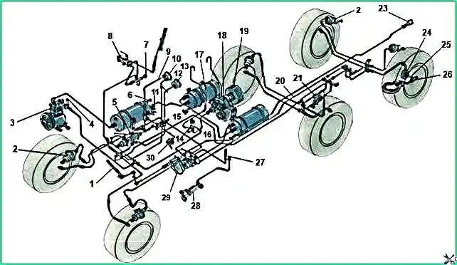
The tire pressure regulation system (see Fig. 1) consists of pressure control valve 5 with a pressure drop limiting valve; heads 24 for air supply to wheel tires, tire valves 26 air locks, air pressure gauge 13 pipelines.
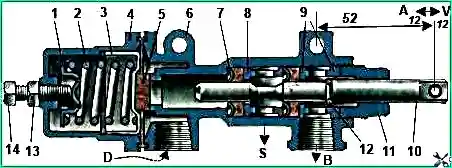
Pressure control valve with a spool valve-limiter (Fig. 2), consists of a housing 6, which has an inlet for supplying air from the pneumatic system to the tires and an outlet for releasing air into the atmosphere.
The spool 10 moves in the body and is sealed by the seals 9, pressed by the spool guide 11, spacer rings 7, bushings 8 and support washers.
Lock ring 12 limits the extreme limits of the spool stroke.
The spool is connected by a rod to the valve lever. The tap lever has three positions; right, left and middle.
All three positions of the lever are fixed in the slots of the bracket and correspond to: the right one for inflating the tires, the middle one for the neutral position when the pressure control system is disconnected from the pneumatic brake system, and the left one for releasing air from the tires into the atmosphere.
When the lever of the pressure control valve is moved to the “Inflation” position (right extreme position), spool 10 moves forward, the groove on the spool is installed against the left oil seal and air enters the tires through the gap formed under the oil seal (tire inflation is turned on).
When the lever of the pressure control valve is moved to the position “Release air to the atmosphere” (left extreme position), the spool moves back, the groove on the spool is installed against the right oil seal and the air from the tires is released into the atmosphere.
The air released into the atmosphere is discharged from the tap through a tube into the engine compartment.
When the pressure control valve lever is moved to the neutral position, the groove on the spool is between the seals, i.e., in a position that excludes both the flow of air from the pneumatic brake system into the tires and the release of air from the tires into the atmosphere (the valve is closed).
The pressure control valve is mounted on a bracket to the left of the driver.
The crane control lever is installed in the slot in the front panel of the cab, on the left side of the driver spruce.
The limiter valve installed on the tap is designed to separate the tire pressure regulation system from the pneumatic brake drive system when the pressure in the latter is reduced to ensure the necessary air supply for reliable braking.
If the air pressure in the brake system is below 5.5 kg/cm 2, diaphragm 5 blocks the flow of compressed air into the tire pressure regulation system.
Tire inflation is only possible when the pressure in the air cylinders exceeds 5.5 kg/cm 2
The valve also allows you to maintain the required pressure in the brake system when the tire pressure decreases.
The valve is adjusted to the specified pressure with a bolt 14, which is secured to the valve cover 4 with a lock nut 13.
Before connecting valve spool 10 to the control lever rod, it is necessary to install the spool so that the size from the hole in the spool for the connecting pin to the nearest bolt is 52 mm (Fig. 2).
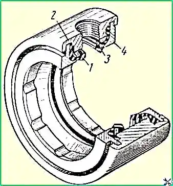
The head for supplying air to the tires is installed inside the wheel journals of the axle shaft and consists of two elastic cuffs 1 (Fig. 3) with pressure springs 3, which ensure the tightness of the movable joint.
Cuffs with pressure springs are mounted in the head body 2 and locked with covers 4, pressed against the stop into the head body by rolling the outer edge of the latter on both sides.
A fitting is screwed into the air supply head through the wheel axle.
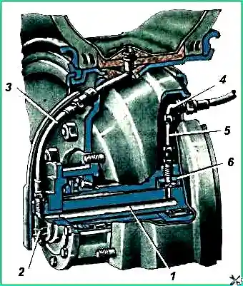
From the cavity of the head formed by the cuffs, air flows through channel 1 into the axle shafts (Fig. 4) to the tire valve 2 and then through the connecting hose 3 through the chamber valve into the wheel tire.
Tire air valves are installed on each wheel.
With their help, tires can be disconnected from the tire pressure control system.
The tire valve is installed in a socket on the axle shafts and secured with four bolts on the axle shaft flanges.
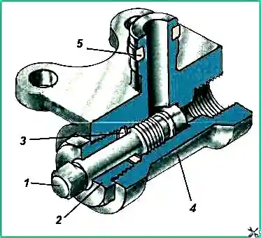
The tap consists of a body 5 (Fig. 5), in which plug 1 moves along the thread, its outer end has a square head for a key.
The plug is sealed with an oil seal 3, which is locked with a nut 2.
The neck of the valve body, which fits into the socket of the axle shaft, is sealed with an elastic ring 4.
Caring for the tire pressure control system
Care for the tire pressure regulation system is as follows.
When servicing a vehicle, you should check the tightness of the system as a whole and its individual elements.
Particular attention should be paid to the tightness of connections of pipelines and flexible hoses, where loosening of the connections can most often occur.
Locations of strong air leaks can be determined by ear, places of weak leaks - using a soap emulsion, which should be moistened with the places of suspected leakage.
Air leakage through pipeline connections is eliminated by tightening them or replacing a separate element of the connection. The tightening torque of threaded connections of air ducts should be 0.4 kgm.
In a working system, the pressure drop in cold tires with the pressure control valve closed and the tire valves on the wheels open should not be more than 0.5 kg/cm 2 for 6 hours of parking the car.
If there is significant damage to the tire pressure regulation system, when the compressor does not compensate for the drop in air pressure in the tires, the tire valves must be closed and the control valve must be placed in the middle position.
If tire valves are damaged, it is necessary to remove the hoses connecting the valves to the wheel valves, insert spool valves into the valves and close the valves with caps.
In this case, you need to inflate the tires, as usual, with a hose, and check the tire pressure with a tire pressure gauge.
The driver must store spool valves and caps for all tires together with small tools.
It is strictly forbidden to disconnect od from the system but or several wheels and use pressure regulation in the rest.
The operation of the air supply heads largely depends on the presence and quality of lubricant on the rubbing surfaces of the oil seal seals and the cover.
Therefore, every time the trunnions are removed, it is necessary to renew the lubricant in the air supply heads.
The inner surface of the oil seal seals and covers must be thoroughly lubricated with lubricant used for wheel hubs; the internal cavity of the heads must be filled with lubricant, except for the area of the inlet fitting.
The pipelines and hoses of the tire pressure regulation system should be periodically blown out.
To do this you need:
- a) release the upper end of the air hose running from the tire valve to the valve, having previously closed the tire valve plug;
- b) drain condensation from air cylinders;
c) start the engine and raise the air pressure in the pneumatic brake system to maximum and blow out each branch of the pipelines.
Tire taps should be kept open at all times. They should only be closed during long-term parking to avoid large air leaks from the tires.
Before driving, the tire valves must be opened and the tires inflated to normal pressure.
In order to close the tire valves, you need to use only a special key, which is included in the driver's tool kit.
The short knob of this wrench does not allow for excessive force.
If the faucet is in good working order, complete tightness is achieved with a low tightening force of the faucet.
An attempt to achieve the tightness of a faulty faucet by increasing the screwing force and using extension wrenches will lead to final damage to the faucet.
It is forbidden to set the tire pressure control valve to the “Inflate” position when the tire valves are closed, as this may damage the tire pressure gauge.
The control valve should be moved smoothly to the “Inflation” position (especially if there is little pressure in the tires), so that a sharp increase in pressure in the air lines does not damage the tire pressure gauge.
")

")
")
")
")
")
")
")