Checking the ZIL-131 pneumatic drive for serviceability
Before driving, make sure that the pressure in the system is not lower than 4.5 kg/cm 2
During driving, the pressure in the pneumatic brake system should be within 5.6-7.4 kg/cm 2
Only a short-term decrease in pressure during frequent repeated braking can be allowed.
To avoid completely running out of air during frequent braking, it is strictly forbidden to stop the engine on long descents.
An increase in pressure above 7.4 kg/cm 2 indicates a malfunction of the pressure regulator or unloading device; an increase in pressure of more than 10 kg/cm 2 also indicates a faulty safety valve.
In this case, it is necessary to immediately eliminate the faults.
When the brake pedal is pressed sharply (with the engine not running), the pressure in the cylinders should decrease slightly (upper scale of the pressure gauge), and the pressure in the brake chambers (lower scale of the pressure gauge) should become equal to the pressure in the cylinders.
After this, there should be no noticeable movement of the pressure gauge needles during the time while the pedal is pressed, a further decrease in pressure in this case indicates a leak in the pneumatic system.
After the brake pedal is sharply released, the time for the pressure to drop in the brake chambers (on the lower scale of the pressure gauge) should not exceed 2 sec.
When the brake pedal is in the free position with the engine not running, the pressure drop in the brake system due to leaks in the system (as indicated by the upper arrow of the pressure gauge) should not exceed 0.5 kg / cm 2 for 30 minutes.
A rapid drop in pressure in the pneumatic system when the engine is stopped indicates an increased air leak from the system.
The location of a large air leak can be determined by ear.
A small leak can be determined using a soap emulsion, which should be moistened on the places of a possible leak.
Air leaks through connections are eliminated by pulling the connecting fittings.
It is necessary to periodically check whether the hoses of the front brake chambers do not touch the wheels turned completely left and right.
To ensure normal operation of the brake system, it is necessary to open the drain valves in the air cylinders during technical inspections and drain condensate.
It is important to remember that condensate can only be drained from cylinders if there is compressed air in them.
A large amount of condensate should not be allowed to accumulate in cylinders, as this may lead to condensate getting into the working devices of the brake system.
The amount of condensate depends on the condition of the compressor and the humidity of the surrounding air; therefore, in wet weather, it is necessary to drain the condensate daily, after finishing work.
The presence of a large amount of oil in the condensate indicates a compressor malfunction.
In winter, it is necessary to especially carefully monitor the drainage of condensate from the air cylinders to avoid freezing it in the pneumatic brake drive pipeline system.
If the condensate freezes, do not heat the cylinders with an open flame (torch, blowtorch, etc.).
Checking and adjusting the pneumatic wheel brake drive
Periodically, it is necessary to check the adjustment of the pneumatic brake drive and the stroke of the brake chamber rods.
The air pressure in the pneumatic brake system must be adjusted in the following order.
When the engine is idling, it is necessary to increase the air pressure in the pneumatic system to 7-7.4 kg / cm 2 (according to the reading on the upper scale of the pressure gauge on the instrument panel); the lower scale reading should be equal to a bullet (air pressure in the brake chambers).
Then press the brake pedal all the way down.
When applying a force of 20-30 kg to the end of the pedal, the air pressure in the brake chambers should equal the air pressure in the cylinders and the arrows on both scales of the pressure gauge should show the same values.
In this case, the end of the pedal should not reach the floor by 10-30 mm.
If the pedal rests on the floor or if the gap does not correspond to the specified one, it is necessary to adjust the amount of travel of the brake pedal by changing the length of the rod connecting the brake valve lever to the intermediate lever of the drive using an adjusting fork screwed onto the threaded end of the rod.
If the brake valve drive is adjusted correctly, then in the presence of compressed air in the air cylinders, the free travel of the end of the brake pedal should be within 40-60 mm.
In addition, it is necessary to check and adjust the air pressure in the connecting line of the pneumatic outlet for controlling the trailer brakes, for this you need to connect the pressure gauge to the coupling head and open the isolating valve.
When unbraked, this pressure gauge should show a pressure within 4.8-5.3 kg/cm 2.
If the pressure gauge reading does not match the specified one, it is necessary to adjust the section of the valve that controls the trailer brakes.
The adjustment should be made in the following order:
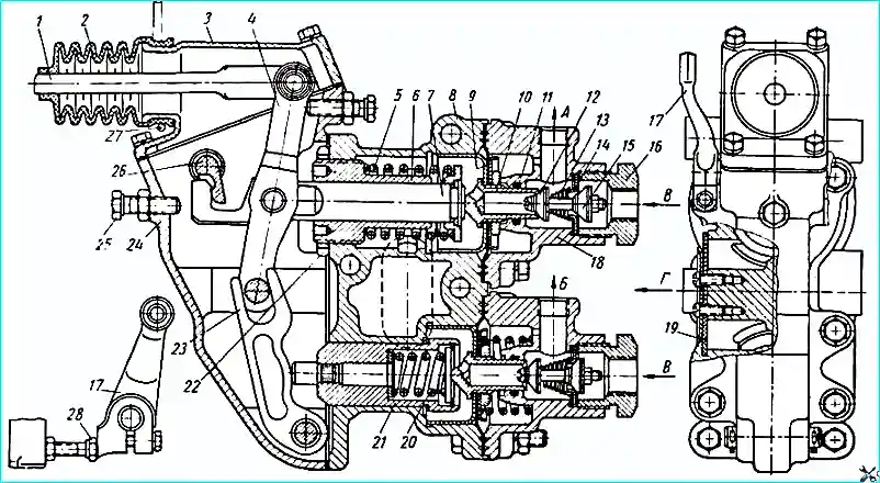
Brake valve: the arrows indicate the direction of air; (A) - into the trailer line; (B) to the brake chambers of the towing vehicle; (C) - from the air cylinder; (D) - into the atmosphere; 1 - brake valve drive rod; 2 - protective cover; 3 - lever housing cover; 4 - large lever; 5 - balancing spring of the section controlling the brakes of the trailer; 6 - rod guide; 7 - rod; 8 - housing; 9 - diaphragm with guide cup; 19 - exhaust valve seat; 11 - sealing ring; 12 - exhaust valve; 13 - valve return spring; 14 - inlet valve seat; 15 - inlet valve; 16 - plug; 17 - hand drive lever; 18 - cover; 19 - exhaust valve; 20 - balancing spring of the section controlling the brakes of the tractor; 21 - balance spring cup; 22 - lock nut; 23 - small lever; 24 - lever housing; 25 - rod stroke limiter; 26 - hand drive lever shaft; 27 - tension clamp; 28 - manual drive lever stop
- remove the housing 24 (see Fig. 1) of the brake valve levers, loosen the lock nut 22 of the rod guide and, by rotating the rod guide 6, set the air pressure supplied to the trailer line within 4.8-5.3 kg / cm 2.
Then tighten the lock nut and put the lever housing back in place (be sure to put the sealing gasket of the lever housing in place).
When smoothly pressing the brake pedal, the pressure on the pressure gauge connected to the coupling head should smoothly decrease and reach zero when the pedal is fully pressed.
The intermediate positions of the pedal should correspond to the intermediate readings of the pressure gauges.
The brake pneumatic system must be checked with the pressure control valve of the regulation system closed air pressure in tires.
")

")
")
")
")
")
")
")