The cardan shaft has two joints. The cardan joint consists of needle bearings 4 installed in the forks and secured with retaining rings 2, and a crosspiece 3 inserted into the bearings
During assembly, 1.8-2.0 g of grease 158, MRTU 12N No. 139-64 are placed in each needle bearing. Rubber rings 5 are used to prevent dirt from getting into the hinge joint.
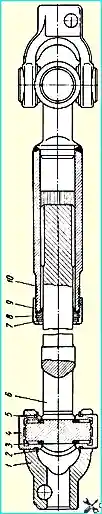
The cardan shaft has a sliding splined connection, which provides the ability to change the distance between the hinges when the cabin oscillates relative to the frame.
The splined connection is lubricated with the grease in it, which must be replaced in accordance with the lubrication chart.
Before assembly, the splines are lubricated with a thin layer, and 18-20 g of grease specified in the lubrication chart is placed in the bushing.
A felt ring 8 and a rubber ring 7 are installed to retain the grease and protect the connection from contamination.
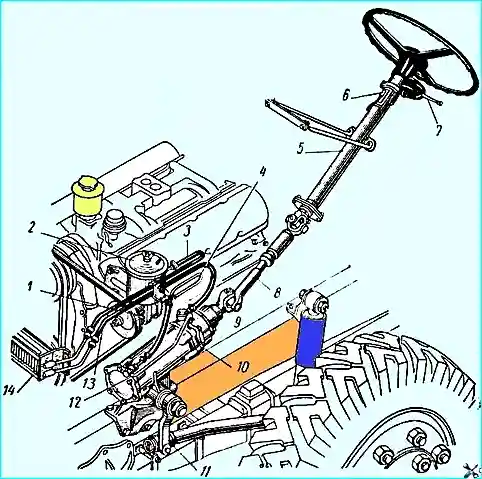
The forks of the cardan shaft are fastened to the steering gear screw and the steering column shaft with wedges 9 (see Fig. 2).
Needle bearings do not require lubrication.
In case of disassembly for any reason, the above amount of grease should be placed in each bearing.
When assembling the cardan shaft, it is necessary to ensure that the holes in the forks for the mounting wedges are in parallel planes and are located as shown in the figure; in this case, the axes of the holes of both forks for the bushings must lie in the same plane.
Retaining rings 2 must be securely installed in the bearing grooves.
The propeller shaft must be installed in such a way that the fork with the splined bushing is at the top.
Steering column
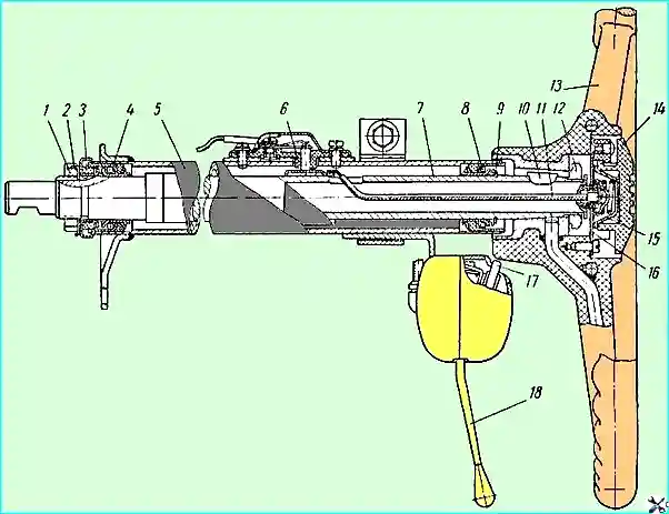
The steering column is attached at the bottom to the cabin floor, and at the top to the front shield and by means of stretchers to the inner panel of the cabin.
Steering shaft 7 rotates in special ball bearings 4, located in the column tube 5.
The axial clearance in the ball bearings is adjusted with nut 1. The tightening torque of nut 12 of the steering wheel should be 6-8 kgm.
Spontaneous loosening of the nut is prevented by bending the tab of the lock washer 2 into the groove of the nut.
The ball bearings are lubricated with grease placed in them during assembly.
The grease should be replaced each time the steering column is disassembled.