ZIL-131 wheels, disc, with split rim and spacer ring, interchangeable, rim size 9.0 RG — 20
Tires of size 12.00—-20, adapted to work at variable pressure
The spare wheel is installed on the car without pressure in the tire and without a valve core.
When assembling the spare wheel with a tire and tube (after repairing the tube), the tire must be inflated to the nominal pressure, after which the air must be released from it.
Without waiting for the air to completely escape from the spare wheel tube valve, the cap must be screwed onto the valve.
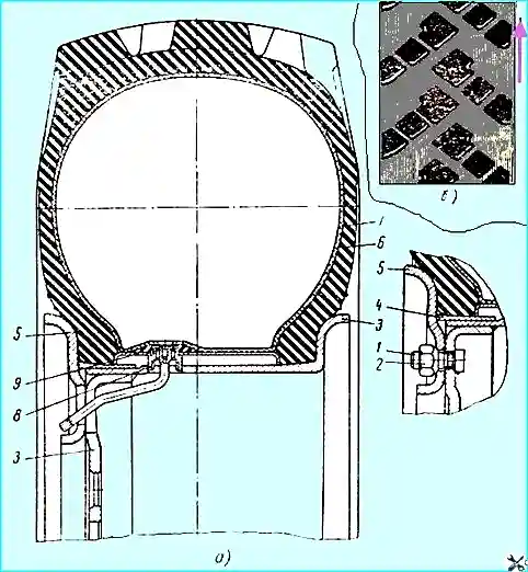
The wheel consists of a rim 3 with a welded disk, a seat ring 4 and a bead wheel 5.
The spacer ring 9 prevents the tire from turning on the rim at reduced air pressure.
The presence of conical shelves on the rim requires especially careful assembly and disassembly of the wheels, compliance with all instructions for maintenance and operation and the use of a mounting tool.
Car tires have a directional tread pattern, and studded wheels must be installed on the car in strict accordance with the direction of the pattern (see Fig. 1, b).
The direction of rotation of the wheels in the figure is indicated by an arrow.
Before assembling the wheel, it is necessary to:
- a) remove dirt, rust and rubber residues from the surface of the wheel, especially from the surfaces of the rim, bead and seat rings, facing the tire;
- b) inspect the wheel externally;
- c) paint the cleaned areas of the wheel parts with quick-drying enamel;
- d) inspect the tire and tube, remove dirt, dry them, sprinkle talc on the inner surface of the tire; the seating surface of the tire beads should not have rubber bulges.
The wheel and tire must be assembled in the following order:
- 1. Place the tire on the side surface with which it will be facing outward, taking into account the direction of the tread pattern.
Put the tube into the tire so that the valve is facing down, and straighten the folds of the tube.
- 2. Open the spacer ring lock. Keep your hands 150-200 mm away from the ring cut.
Insert the spacer ring into the tire so that the valve hole is facing down.
- 3. Insert the inner tube valve into the valve guide hole of the spacer ring and close the lock using a straight tire iron.
- 4. Center the spacer ring relative to the tire beads using light blows from the hammer handle.
- 5. Insert the rim into the tire so that the valve guide on the spacer ring aligns with the valve groove on the rim.
- 6. Turn the tire and rim upside down with the bolts facing up and insert the seat ring between the rim and the tire bead.
- 7. Install the bead ring so that the nuts can be screwed on and tightened. The tightening torque should be 25-35 kgm.
The tire beads are clamped with 17 nuts 2 on bolts 1 using a bead ring 5. The nuts and bolts have right-hand threads on all wheels.
The bead ring mounting nuts should be tightened evenly, alternately tightening the opposite nuts.
- 8. Inflate the tire to a pressure of 3 kg/cm2.
The tire should be disassembled in the following order:
- 1. Release all air from the tube.
- 2. Loosen the four nuts located diametrically opposite each other.
- Then, one by one, loosen the remaining nuts and unscrew them.
Last of all, unscrew the four nuts that were loosened earlier.
Do not unscrew the bead ring nuts without first releasing the air from the tire.
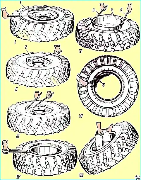
- 3. Remove the bead ring with the flat end of a straight mounting blade (position 1 in Fig. 2).
- 4. Remove the seat ring, for which; insert the mounting blade with a curved grip into the groove located near the cut in the seat ring on the inside and press the mounting blade down (position II) repeat the operation relative to the remaining grooves.
Repeat this procedure several times and ensure that the end of the seat ring the ring on which the grooves are located was removed;
- - insert the straight mounting blade with the straight end between the end of the rim and the curved part of the seat ring, fix this position;
- - also place the curved end of the mounting blade with a curved grip between the end of the rim and the seat ring and press it down (position III), thus acting to completely remove the seat ring.
- 5. Turn the wheel over, insert a straight tire iron between the rim flange and the tire bead until it stops against the rim and press it down.
Insert a tire iron with a curved grip into the resulting gap between the tire and the rim.
Press both tire irons in this engagement down (position IV).
Repeat the previous operation around the entire circumference until the tire bead is completely removed from the conical shelf of the rim.
If you cannot remove the rim by hand, then it must be removed from the tire using the technique shown in Fig. 1 (position V).
- 6. Place the tire vertically, push the valve into the tire cavity through the valve guide hole on the spacer ring.
Open the spacer ring lock using the mounting blade (position VI), then turn the ring inside the tire by 90° and remove it completely (position VII).
The wheel is attached to the hub with eight studs.
To prevent the wheel nuts from loosening, the studs of the right-hand hubs have a right-hand thread, and the studs of the left-hand hubs have a left-hand thread.
To indicate the left-hand thread, the nuts have a circular cut at the corners of the edges, and on the studs - on the end.
When putting on the wheels, the nuts securing the wheels to the hubs must be tightened evenly crosswise, alternately tightening the opposite nuts.
The tightening torque of the wheel nuts must be at least 40 kgm.