The non-contact shielded ignition system is installed on the ZIL-1Z1 car and its modifications
The ignition system diagram is shown in Fig. 1.
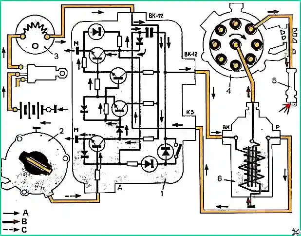
The system consists of an ignition coil B118, a distribution sensor 4902.3706, a transistor switch TK200-01, spark plugs SN-307V, high-voltage wires in shielding hoses and manifolds, an ignition switch VKZ50 and an additional resistor SEZ26, which is automatically short-circuited when the engine starts.
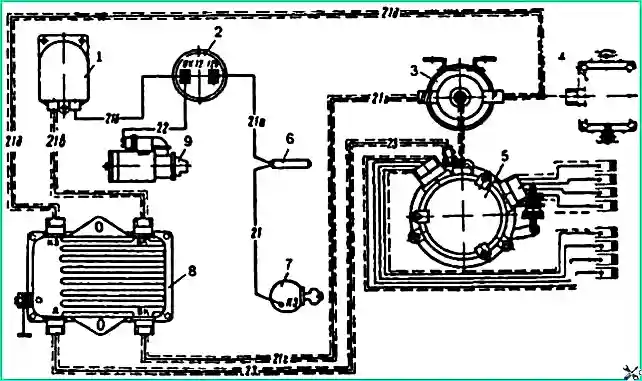
To protect radio reception from interference created by the ignition system, a radio interference suppression filter FR82F is included in the power circuit of the ignition system.
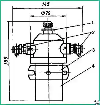
Ignition coil B118 (Fig. 2) shielded, sealed.
Unlike other ignition coils, one end of the secondary winding is connected internally to the coil body.
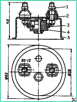
The additional resistor (Fig. 3) is unshielded, designed to limit the electric current flowing in the ignition system circuits in operating and emergency modes.
Nichrome spiral 3 is mounted on a porcelain insulator 4 in a stamped metal case 5.
The ends of the spiral are connected to output terminals 1, mounted on insulating sleeves 2 installed in the metal bottom of the housing.
When replacing the spiral, the additional resistor is removed from the car.
Transistor switch is designed for switching electric current in the primary winding of the ignition coil (breaking the primary circuit of the ignition coil at the required moment by turning on a large ohmic resistance of the output transistor)
The transistor switch is installed on the left wall in the car cabin and can only operate at an ambient temperature of no higher than 70˚ C and no lower than minus 60° C.
It cannot be repaired under operating conditions and, in case of failure, is replaced.
To check the functionality of the switch on the bench, it is necessary to assemble a diagram of the contactless ignition system (Fig. 1▲)
By turning on the supply voltage (12.6 ± 0.6) V and changing the rotation speed of the sensor-distributor from 20 to 1600 min -1, you can observe a stable spark at the arresters.
When using a generator instead of a sensor, a sinusoidal output voltage with an amplitude of 2 - 10 V is set on the generator and, by changing the generator rotation frequency from 2.6 to 213 Hz, a stable spark can be observed on the spark gap connected directly to the ignition coil.
No sparking indicates a faulty switch that needs to be replaced.
The protection of the switch against an emergency increase in the supply voltage occurs at a rotation speed of the sensor-distributor roller of 1000 min -1 or a generator signal frequency of 135 Hz by smoothly increasing the supply voltage until sparking completely stops, but not more than 23 V.
When checking the functionality of the non-contact ignition system devices on a car, it is necessary to remove the screen cover of the sensor-distributor, pull out the high-voltage wire from the central socket of the distributor cover; by setting a gap between the end of the tip of the high-voltage wire and the housing of the distribution screen caster 4 - 6 mm, turn on the ignition, and turn the crankshaft with a starter or crank at a rotation speed of at least 40 min -1.
The presence of a spark discharge in the gap indicates the serviceability of the ignition system as a whole.
If there is no spark in the gap, you must disconnect the low-voltage connector from the sensor that goes to the input “D” of the switch, and touch the connector plug to any point in the vehicle’s on-board network that is energized with 12 V (the terminal of the additional resistor, the “+” terminal of the battery batteries).
The presence of a spark in the gap between the end of the tip of the high-voltage wire and the screen body indicates a malfunction of the distribution sensor, and the absence of a spark indicates a malfunction of other devices.
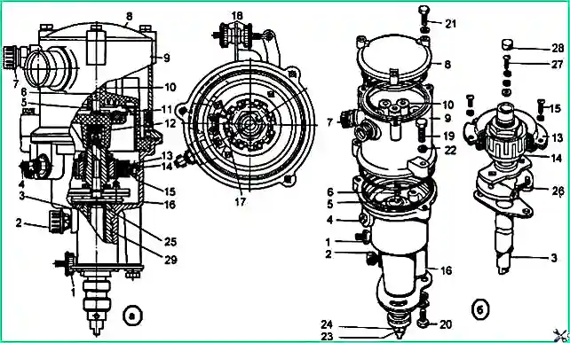
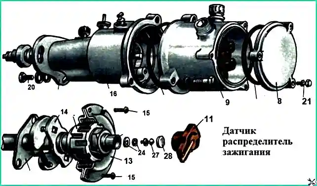
Sensor-distributor 49.3706: a - device of the sensor-distributor; b - parts of the sensor-distributor; 1 - octane corrector nut; 2 - oiler; 3 - distributor roller with automatic transmission and rotor; 4 - low voltage output terminal; 5 - contact angle; 6 - contact carbon spring, 7 - output of the high-voltage wire to the ignition coil; 8screen cover; 9 - screen; 10 - distributor cap; 11 - runner, 12 oil seal; 13 - stator; 14 - rotor; 15 - screw; 16 - distributor housing; 17 - ignition setting mark, 18 adjusting nut; 19,20 and 21 - bolts, 22 - spring washer; 23 - pin; 24 and 29 - bushings; 25 - bearing GPZ2018; 26 - spring; 27 - screw; 28 - filz
Distributor sensor (see Fig. 4) is shielded, works in conjunction with the B118 ignition coil, is designed to control the operation of the switch, distribute high-voltage pulses across the engine cylinders in the required sequence, for automatic control of torque advance ignition depending on the crankshaft speed, as well as to set the initial ignition timing.
Removing the distributor sensor from the engine
There are two ways to remove the distributor sensor from the engine:
- - disconnect the fastening of the brackets of the spark plug wires, unscrewing these wires from the spark plugs, disconnect the wires of the low-voltage and high-voltage terminals on the sensor-distributor and, having unscrewed the two bolts securing the sensor-distributor to the block, remove it from the engine along with the spark plug wires and their brackets,
- - unscrew the low-voltage and high-voltage wires from the terminals of the sensor-distributor, unscrew the bolts (see Fig. 4) and remove the screen cover 8.
Then remove the spark plug wires of the distributor sensor, unscrew bolt 20 securing the adjusting plates, and remove the distributor sensor from the engine.
Care must be taken not to drop bolt 20 and washers into the engine.
Disassembling the ignition sensor-distributor
To disassemble the ignition sensor-distributor, you need to secure it in a vice to the housing 16 and, unscrewing the bolt securing the screen 9 to the housing, protecting the rubber O-rings from falling out or damage.
Remove cover 10 and slider 11, unscrew two screws 15 and remove the stator assembly using a punch or unscrew it.
Using a punch, knock out pin 23 from roller 3, remove sleeve 24 assembled with the washer, and remove roller 3 assembled with the centrifugal regulator and rotor 14.
After this, remove the support bearing 25 with the plate from the housing 16.
To remove the rotor 14 from the roller, you need to remove the felt 28 and unscrew the screw 27.
Spring 26 of the regulator can be easily removed from the racks using pliers or a screwdriver.
Checking the parts of the distributor sensor
After disassembling, all parts of the sensor-distributor must be washed with kerosene or gasoline and wiped dry with a napkin.
After this they must be carefully examined.
Cracks, chips, burnouts of high-voltage leads and other defects are not allowed on the distributor cover 10.
It is necessary to check the freedom of movement of the coal in the socket and the lid and replace it if it is severely worn.
Then you need to check the play of the roller 3 in the housing 16 and, if present, press out the two bushings 29, replacing them. If there are defects in springs 26, they must also be replaced.
To check the functionality of rotor 14, connect a tester or test lamp with a battery to the winding terminal and to the low-voltage output plate and determine whether the winding is broken.
If there is a break in the winding, the rotor must be replaced.
Assembling the distributor sensor
Before starting assembly, lubricate the surface of roller 3 with engine oil, install rotor 14 on it and secure the screws volume 27.
Then add 2-3 drops of engine oil to screw 27 and place filter 28 in the rotor hole.
Install, if they were removed, springs 26 onto the plastic racks.
Next, install support bearing 25 into housing 16, lubricating it and the support washer installed on top of it with Litol-24 lubricant.
Then insert roller 3 assembled with the rotor into housing 16, put a washer and bushing 24 on its lower end and install pin 23 into the hole on the roller, loosening it with a core.
Install stator 13 into housing 16, placing it with terminals with wires facing up.
In this case, after wiping it with alcohol, place the low-voltage terminal plate opposite terminal 4 of housing 16. Secure the stator with two screws 15.
Install slider 11 on the roller and close the distributor with cover 10, aligning the grooves in the cover and body 16.
Having checked the presence of rubber sealing rings in housing 16, install screen 9 on the housing and secure it with bolts 19. After this, fill oiler 2 with Litol-24 lubricant.
When assembling terminal 4, it is necessary that wire 7 is soldered to pin 9, and the shielding braid 1 is well tucked in and clamped with washers 4 and 5.
To check the functionality of the distribution sensor, it must be installed on a test bench and checked.
- - characteristics of the centrifugal machine;
- - maximum voltage at the low-voltage input, which should be 45 V at a roller rotation speed of 1600 min -1.
The distribution sensor must provide an amplitude value of the output voltage, which has a shape close to sinusoidal, of at least 1.4 V at a load equivalent of 3.9 kOhm at a roller rotation speed of 20 min -1.
Installing the ignition distributor sensor on the engine
The installation of the ignition distributor sensor on the engine is carried out in the reverse order of its removal.
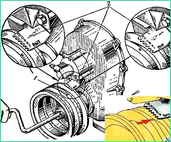
The crankshaft pulley mark must coincide with mark 9 on the ignition timing indicator.
")

")
")
")
")
")
")
")