Radiator tubular-ribbon, with oval-section tubes, four-row
Radiator filler cap (Fig. 1) is sealed with two valves; inlet (air) and outlet (steam)
The outlet valve, loaded with a spring, maintains a pressure of 1 kg/cm 2 in the cooling system.
At this pressure, the boiling of the coolant occurs at a temperature of 119˚ C
Therefore, a reserve of efficiency of the cooling system is created and the car can be operated in difficult conditions for a longer time with non-boiling water in the radiator.
If rubber washers 6 and 11 of the radiator cap valves are missing or damaged, then the cooling system stops working as a closed system, and the boiling of the liquid in this case occurs at 100˚ C.
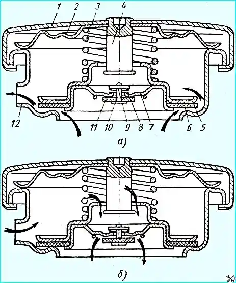
Radiator cap: (a) - opening of the outlet (steam) valve; (b) - opening of the inlet (air) valve; 1 - cap cover; 2 - thrust spring washer of the cap; 3 - spring of the outlet (steam) valve; 4 - stem of the outlet valve; 5 - plate of the outlet valve; 6 - sealing washer of the outlet valve; 7 - cup of the inlet valve (air); 8 - spring of the inlet valve; 9 - washer of the inlet valve; 10 - stem of the inlet valve; 11 sealing washer of the inlet valve; 12 - steam outlet
The inlet valve, loaded with a weaker spring, prevents the creation of a large vacuum in the system when the engine cools down and protects the radiator parts from damage.
The inlet valve opens and connects the radiator cavity with the atmosphere when the pressure drops by 0.01-0.13 kg/cm.
The temperature of the coolant in the cooling system is monitored by an indicator installed on the instrument panel.
The temperature gauge sensor is located in the water channel of the engine intake pipe.
When the coolant temperature reaches 115° C, the coolant overheating warning lamp lights up on the instrument panel, the sensor of which is located in the upper radiator tank.
In this case, you should open the radiator or expansion tank cap carefully, since a sharp When opening the plug, hot water may be thrown out of the neck.
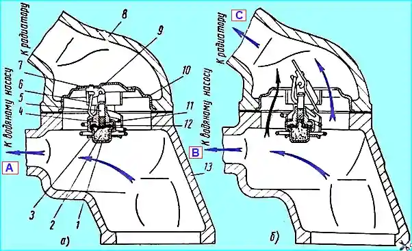
Thermostat operation diagram: a - thermostat in the closed position; b - thermostat in the open position; 1 - thermostat cylinder; 2 - active mass, ceresin); 3 - membrane; 4 - guide sleeve; 5 - rod; 6 - return spring; 7 - thermostat flap; 8 - upper branch pipe; 9 - flap rocker; 10 - thermostat housing; 11 - buffer: 2 - rim; 13 - lower branch pipe; (A) - to the water pump; (B) - to the water pump; (C) - to the radiator
The thermostat with a solid filler is placed between the upper and lower pipes of the water jacket.
The thermostat serves to accelerate the warming up of a cold engine and protect it from overcooling.
When warming up a cold engine, the channel connecting the engine jacket to the radiator is blocked by the thermostat flap 7 (Fig. 2).
The coolant through the bypass pipe connecting the lower outlet pipe of the water jacket with the suction cavity of the water pump bearing housing circulates intensively, bypassing the radiator, which accelerates the warming up of the engine.
This circulation is maintained until the thermostat is fully open.
When the coolant reaches a temperature of 70-83 ° C, ceresin (petroleum wax) 2 (Fig. 2, b), enclosed in the thermostat cylinder 1, melts and, increasing its volume, causes the rod 5 to move upward and opens the damper 7, after which the coolant begins to circulate through the radiator.
As the temperature decreases, the ceresin decreases its volume, and the damper closes under the action of the spring (Fig. 2, a).
The radiator blinds are used to regulate the air flow passing through the radiator; the blinds are controlled from the driver's cabin.
The control handle is located under the shield on the left side of the cabin.
To close the blinds, pull the handle towards you.
The blinds should be closed when the engine is warming up, as well as when driving if the coolant temperature drops.