The B10 fuel pump is a diaphragm, sealed, with three outlet and three inlet valves and a lever for manual fuel pumping
The pump is installed on the left in the upper part of the engine and is driven by the camshaft eccentric using a rod.
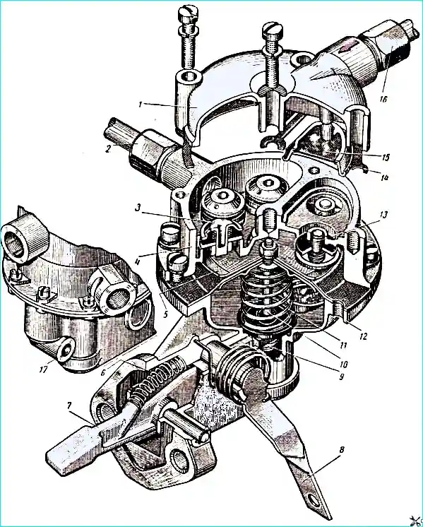
The pump consists of three main parts (Fig. 1): cover 1, head 4 and housing 12, die-cast from zinc alloy.
The housing contains a rocker arm 7 with a return spring 6 and a lever 8 for manual fuel pumping.
A diaphragm 5 is fixed between the housing and the head of the fuel pump, which is assembled on a pusher 10 with two plates.
The rocker arm acts on the pusher through a textolite support washer 9.
A return spring 11 is installed under the diaphragm.
The pump head has three inlet valves 13 and three outlet valves 3.
When the diaphragm moves down, fuel from the tank passes through a mesh filter 15 through a tube inlet valves.
When the diaphragm moves upward, fuel is pumped through the outlet valves 3 into the head cavity, from where it is directed to the fine filter and then to the carburetor:
Depending on the fuel consumption, the amount of fuel supplied by the pump also changes.
A change in consumption causes the fuel level in the float chamber to fluctuate and, consequently, changes the shut-off force of the carburetor needle valve; therefore, a back pressure is created in the fuel line connecting the pump to the carburetor, which is greater the less the needle valve is open, i.e. the lower the fuel consumption.
With back pressure, the diaphragm moves up in accordance with the fuel consumption at the moment.
Pump capacity 180 l/h (not less) at 2600-2800 rpm of the engine crankshaft.
Maximum pressure at zero feed no more than 225 mm Hg. st.
During operation, check the pump for leaks daily and eliminate fuel leaks if necessary.
If the fuel supply is insufficient, check the condition of the diaphragm by observing whether there is a leak through inspection hole 17.
If the diaphragm is damaged, fuel will flow out of the hole.
Do not disassemble the fuel pump unnecessarily to avoid fuel leaks between the joint planes of the cover, head and body.
When disassembling the pump, remove the mesh and wash it in clean gasoline.
Disassemble and assemble the pump carefully so as not to damage the diaphragm and gasket.
When replacing the diaphragm, carefully tighten the pusher nut so as not to accidentally damage the sheet of diaphragm rubberized fabric.
When assembling the diaphragm, make sure that no dust particles, sawdust; metal shavings, etc., as this leads to rapid wear of the diaphragm.
When assembling the fuel pump head with the housing, the connecting screws should be tightened with the diaphragm pressed down by the manual pumping lever.