The vehicle's driveline consists of four driveshafts: the main one between the gearbox and the transfer case, the middle axle drive between the transfer case and the middle axle reduction gear, the rear axle drive between the reduction gears of the middle and rear axles, and the front axle drive between the transfer case and the front axle reduction gear.
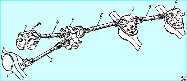
The design of all cardan shafts is the same (Fig. 2); The middle axle drive cardan shaft is larger in size than all the others.
Each cardan shaft consists of a thin-walled pipe, to one end of which a fixed hinge fork is welded, and to the other end a splined sleeve 9, connected to the sliding hinge fork.
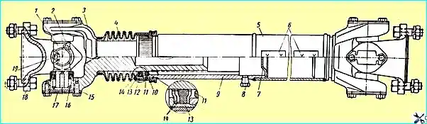
All eight cardan joints are identical in design and each consist of a fixed or sliding fork, a fork flange 18 and a crosspiece 1 installed in the fork ears on needle bearings 16.
The bearings of the joints are lubricated through an oiler 2 screwed into the body of the crosspiece.
The lubricant is supplied to the bearings through axial channels.
Rubber seals mounted in the bearing cage serve to retain the lubricant.
In the center of the crosspiece there is a safety valve 19, through which, when the crosspiece is filled with oil, excess oil comes out, thereby protecting the seals from damage as a result of increased oil pressure.
The cardan shafts have a sealed splined connection.
The grease in the inner cavity of the bushing is kept from leaking by the plug 7, rolled into the splined bushing 9, as well as by the rubber 11 and felt 13 rings.
Both rings, in combination with the protective coupling 4 of the splines, prevent contamination of the splined connection.
The protective coupling is secured to the shaft with two threads of cotter wire.
The cardan shafts are dynamically balanced.
Balancing of all cardan shafts, except for the main one, and the rear axle shaft is achieved by welding balancing plates 6 to the ends of the pipe.
Balancing of the rear axle cardan shaft and the main cardan shaft on the blind fork side is achieved by welding balancing plates to the pipe, and on the sliding fork side - by screwing the balancing plates to the ends of the fork ears.
There is no protective clutch on the main propeller shaft connecting the gearbox to the transfer case.
Caring for propeller shafts
When operating the vehicle, the following is necessary:
- 1. Regularly check the fastenings of the propeller shaft flanges. All fastening bolts must be tightened to failure.
- 2. If the bolts securing the support plates of the crosspiece bearings are loose, tighten them (the tightening torque should be 1.4-1.7 kgm).
If there is significant radial and end clearance in the crosspiece bearings, disassemble the joints and, if necessary, replace the bearings or crosspieces.
- 3. Periodically check the clearance of the splined connection. If the gap is large due to wear of the splines, the shaft must be replaced.
- 4. When disassembling the joint of the rear axle cardan shaft and the main cardan shaft, mark the balancing plates screwed to the ends of the fork ears so that they can be put back in their original place during assembly.
After assembling the cardan shaft, it is necessary that the arrows stamped on the tubular shaft and sliding fork are located opposite each other; the grease nipples of the crosspieces must be facing the shaft (for ease of lubrication), and not towards the flange; The crosspieces must rotate in the bearings without jamming.
The bolts securing the support plates of the needle bearings must be tightened and locked by bending one eye of the locking plate to the edge of the head of each bolt.
After replacing individual parts, the cardan shaft must be dynamically balanced by welding plates 6 or installing removable plates under heads of the bolts for fastening the support plates of the crosspiece bearings, for all shafts except the shaft of the middle bridge, the permissible imbalance is no more than 70 gcm, and for the shaft of the middle bridge 100 gcm.
The total thickness of the removable balancing plates must be no more than 3 mm.
- 5. Strictly observe the lubrication periods for the cardan transmission according to the lubrication chart.
Lubricate the needle bearings 16 (Fig. 2) through the oiler in the crosspiece until oil begins to flow out of the safety valve.
Before lubricating the crosspieces of the cardan shafts, it is especially necessary to thoroughly clean the grease nipples from dirt.
When adding grease, it is squeezed out of the safety valve after five to eight pumpings of the lever-plunger syringe.
If there is no grease in the joint, it is squeezed out of the safety valve after 45-50 pumpings of the lever-plunger syringe.
To lubricate, disassemble the splined joints, unscrew the plug 8; wash the splines of the sliding fork and the inner cavity of the splined bushing, put fresh grease into this cavity and reassemble the shaft.
After assembling the shaft, put plug 8 back in place.
When lubricating the splined connection, it is necessary to use a certain amount of grease specified in the lubrication chart.
It is forbidden to add grease through plug 8 in the splined connection without disassembling the cardan shaft.
When assembling the splined connection, it is necessary to ensure that the split washers 14 of the felt ring 13 are installed with the split in different directions.