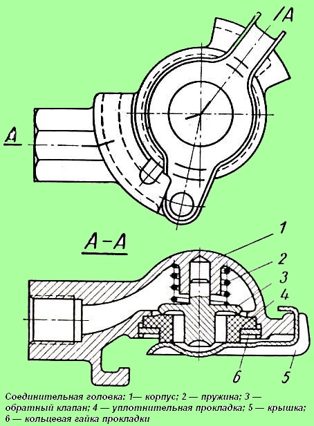
The coupling head is used to connect the air ducts of the vehicle to the trailer
The cover 5 protects the system from dust and dirt.
If the coupling head of the vehicle is not connected to the head of the trailer, cover 5 must always be closed. At the same time, the disconnect valve located in front of the head must also be closed.
Before connecting the heads of the tractor and trailer, open the cover 5, press the valve 3 and, turning the handle of the release valve.
Blow out the head.
Then you need to connect the heads and open the disconnect valves on the car and trailer.
Before each trip, you must check that the disconnect valve is open.
When disconnecting the connecting heads of the tractor and trailer, you must first close the disconnecting valve, then disconnect the heads and then be sure to close the covers of 5 heads that protect the heads from dirt.
If air escapes between the connection heads, check the condition of the rubber seals 4 and replace them if necessary.
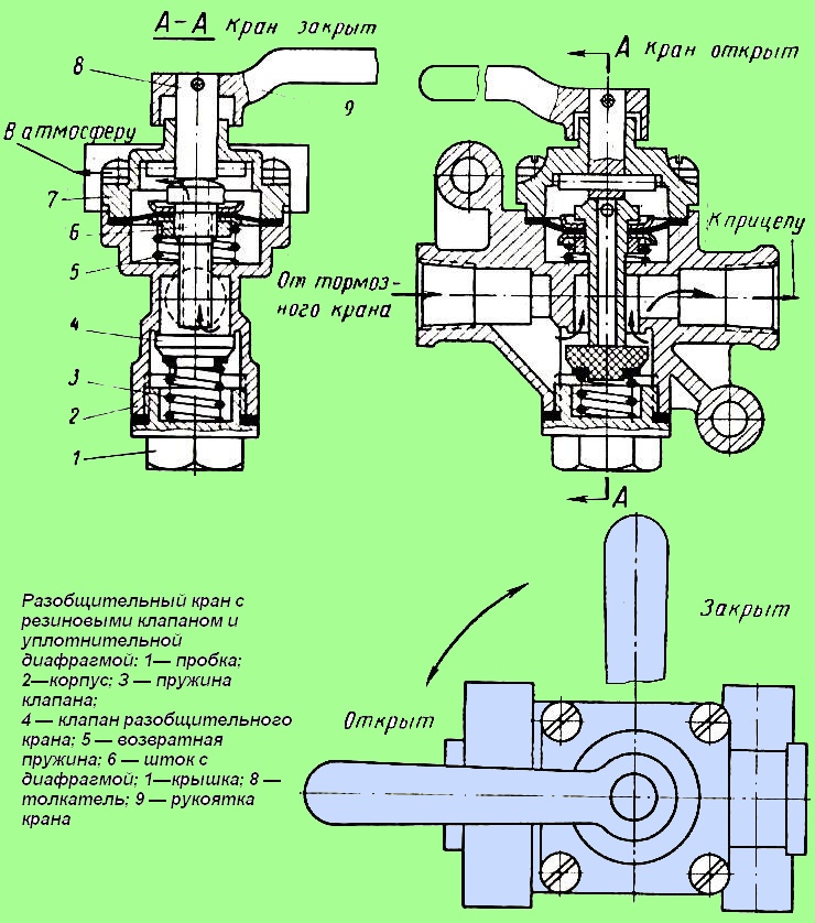
Disconnect valvewith a rubber valve and a sealing diaphragm is installed in the line connecting the tractor and trailer in front of the coupling head, and serves to disconnect the line.
The faucet is open when its handle is directed along the faucet body, and closed when the handle is located across the body.
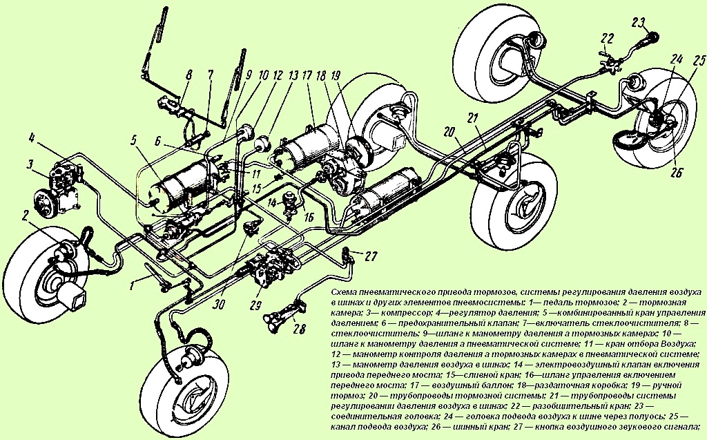
Air bleed valve 11 (see fig. 3) is designed to bleed air from air tanks and is located on the right front air tank.
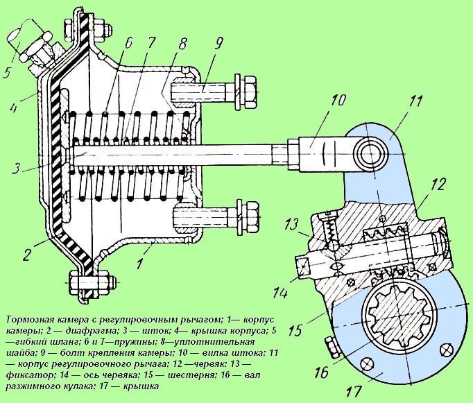
Brake chambers are designed to actuate the wheel brakes - the car.
The rod 3 of the brake chamber with the help of a fork 10 and a pin is connected to the adjusting lever 11 of the brake expansion cam.
The tightness of the brake chambers should be checked during TO-2. to do this, pressing the brake pedal, fill the chambers with compressed air, then moisten the edges of the brake chamber flange, the passage of the bolts tightening the flange, the passage of the rod through the chamber body, the holes in the body and the place where the pipeline is connected to the chamber with soapy emulsion.
Air leakage is detected by the formation of soap bubbles. To eliminate the leak, it is necessary to evenly tighten all the bolts securing the chamber cover.
If the air leak continues, then you need to change the chamber diaphragm.
In case of deformation of the body or cover, they must be straightened.
The service life of the brake chamber diaphragm is 2 years. At the end of this period, it is recommended to replace the diaphragm.


