Generator G51 is waterproof, operates in parallel with the battery and together with the relay-regulator PP5I, designed to supply consumers with electricity and recharge batteries
DC generator, four-pole, protected design, shielded, parallel excitation with internal blowing from a fan cast together with pulley 11.
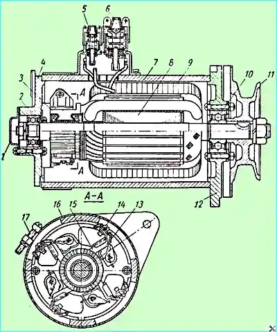
Generator: 1 - bearing cover; 2 - bearing on the collector side; 3 - collector; 4 - generator cover from the collector side; 5 - output shielded terminal of the shunt winding (Ш); 6 - output shielded terminal of the armature winding (Я); 7 - generator housing; 8 - armature; 9 - excitation winding; 10 - bearing from the drive side; 11 - pulley with fan; 12 - cover from the drive side; 13 - brush holder spring; 14 - brush holder; 15 - brush; 16 - protective tape; 17 – screw of protective tape
In covers 4 and 12 there are two bearings 2 and 10 of closed type (with rubber seals), in which anchor 8 rotates.
On the cover on the collector side there are four reactive type brush holders.
The rated voltage of the generator is 12 V, power 450 W.
The generator allows immersion in water, but cannot work in water due to severe wear of the brushes.
When the ZIL 131 vehicle overcomes a ford deeper than 0.7 m, the generator drive must be disconnected.
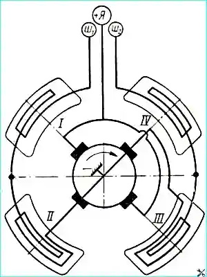
The electrical diagram of the generator is shown in Fig. 2.
The negative brushes are installed in non-insulated brush holders and connected to the generator housing.
The positive brushes are installed in insulated brush holders and connected to terminal "Я".
The two ends of the two pairs of generator excitation winding coils are connected to terminals (Ш), and the other two ends of these coils are connected to the housing.
Terminals Ш1 and Ш2 and terminal 51 go inside a special shielding box attached to the housing.
The generator rotates right, when viewed from the drive side.
To ensure that the generator can operate after being in water, improved insulation impregnation and special materials are used; other parts have improved protective coatings that are resistant to corrosion.
There are special holes in the protective tape for water drainage.
The generator is attached to the brackets with two paws, which in turn are fixed to the compressor base.
The rear bracket has oval holes that allow it to be moved to select the gap between the brackets and the paws.
The third paw is designed to attach the generator to the tension bar, which is used to adjust the tension of the drive belt.
For ease of adjustment, the slot in the bar is made not on the generator side, but on the side of the compressor base.
The anchor shaft bearings have built-in rubber seals and operate without adding grease.
The generator operation is monitored on the vehicle using a control lamp installed on the instrument panel.
The control lamp is connected between ignition switch and the "I" terminal of the generator.
When the ignition is turned on and the engine is not running, the lamp should glow at full intensity.
After the engine starts, as the crankshaft speed increases, and consequently the generator anchor speed, the lamp glows less.
When the generator develops normal voltage, the lamp goes out completely.
If the control lamp lights up at 900-1000 rpm and higher, this indicates a malfunction of the generator or regulator relay.
If the lamp does not light up when the ignition is turned on, it has burned out and must be replaced immediately.
The wires from the regulator relay must be connected to the generator output terminals in strict accordance with the general electrical equipment diagram.
The parts installed on each generator and regulator relay are pre-connected to the ends of the wires. plug connector and shield braid fastening (plug, conical and rubber bushings, special nuts).
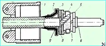
Wire termination sketch: 1 - nut on the shielded wire side; 2 - inner conical bushing; 3 - outer conical bushing; 4 - contact plug cup; 5 - nut with sides of the contact plug; 6 - contact plug; 7 - washer; 8 - rubber bushing; 9 - shielding braid
Connection of wires to the contact plugs of the generator and voltage regulator plug connectors is shown in Fig. 3 and is done as follows:
- - strip the end of the wire at a length of 20 mm, put nut 1 and outer conical sleeve 3 on the shielding braid of the wire;
- - pull the shielding braid onto the inner conical sleeve 2, which is clamped with the help of sleeve 3.
Bend the tabs of the braid and connect it to sleeve 2.
In this case, it is necessary to carefully cut off the protruding veins of the shielding braid so that these veins do not touch the conductive parts, then put the rubber sleeve 8 attached to the connector on the end of the wire.
On the contact plug, unscrew nut 5, remove washer 7 and cup 4.
Insert the stripped end of the wire into the hole of the contact plug 6 from the side of the insulating collar and wrap the end of the wire once around the threaded part of the contact plug, put on cup 4, washer 7 and tighten nut 5 tightly.
When threading the wires, make sure that individual wires of the core do not protrude from under cup 4, otherwise they can cause a short circuit.
Technical characteristics of the generator
Rated voltage in - 12
Rated current in A - 35
The number of revolutions of the generator shaft per minute at which a voltage of 12.5 V is achieved at a temperature of 20 ° C:
- at a current equal to zero - 1450
- at a current equal to zero
No-load current (at a voltage of terminals 12 V) when the generator is operating in the engine mode in A, no more than 12
The force of pressure of the brush springs on the brushes in G is 800-1300
Generator maintenance
It is necessary to check the tension of the drive belt daily.
During the first maintenance:
- 1. Clean the outer surface of the generator from oil and dirt.
- 2. Check the reliability of the generator fastening to the bracket, as well as to the tension bar.
When fastening the generator to the engine, it should be taken into account that the rear generator bracket has oval slots for the bolts that fasten the bracket to the base of the air compressor.
Thanks to this, the brackets can be pulled to the generator cover paws without a gap.
When installing the generator, before tightening the generator fastening bolts to the brackets, it is recommended to loosen the rear bracket bolts, tighten the generator fastening bolts, and then fully tighten the rear bracket bolts.
- 3. Check the tightening of the nuts, contact forks; To do this, unscrew the special union nuts of the connector, remove the plugs and check the tightness of the plugs.
- If the plugs wobble, tighten the nuts.
When tightening and unscrewing the union nuts of the connectors, prevent the shielded wires from twisting along the nut, as this leads to the destruction of the shielding braid, as well as to a breakdown of the electrical contact between the wire braid and the body.
Tighten the union nuts only by hand.
Use pliers or other tools only as a last resort; do not allow damage to the nipples or the union nuts themselves.
During the second maintenance (5,000-6,000 km) and after each fording:
- 1. Check the operation of the brush assembly. To do this, remove the generator protective tape, inspect the brushes and collector, and make sure that the brushes move freely in the brush holders and fit well against the collector.
- 2. Check the pressure of the brush springs with a dynamometer.
The pressing force of the brush springs must be at least 0.6 kg. The height of the brushes must be at least 14 mm.
Worn brushes must be replaced with new ones. New brushes must be ground to the commutator.
New brushes are ground to the commutator as follows: insert a strip of fine glass paper with a width equal to the length of the commutator between the brush and the commutator. To do this, pull the brush holder lever with a wire hook and lift the brush.
The strip must cover at least half the circumference of the commutator (more than 180°) and be facing the brushes with its working side.
Then release the brushes and drag the strip against the direction of rotation of the anchor until the brushes fit tightly to the commutator.
When moving in the direction of rotation, the brushes must be lifted.
- 3. Check the condition of the working surface of the commutator; it should be clean and not burnt.
If there are dirty or burnt surfaces, wipe the collector with a clean cloth soaked in gasoline.
During normal generator operation, the working surface of the collector looks like a surface treated with polish.
Do not mix a burnt collector, which has a matte black color at the tapering edge of the plastictin, with a non-burnt collector, having a shiny working surface of light brown or blue color.
It is not necessary to clean the shiny surface of the collector, since such a surface improves the operation of the brushes.
If the dirt or burnt-on deposits are not removed with a rag soaked in gasoline, it is necessary to clean the collector with fine glass sandpaper, rotating the anchor by hand.
It is not allowed to use sandpaper.
If the burnt-on deposits are not cleaned with glass sandpaper, it is necessary to remove the generator from the engine, disassemble it and grind the collector until a clean smooth surface is obtained.
After grinding, it is necessary to clean the collector, i.e. select the insulation between the collector plates to a depth of 0.8 mm with a sharp hacksaw blade sharpened to the depth of the insulation.
The cleanliness of the processing after grinding should be at least «7».

When cleaning, ensure that the insulation is selected across the entire width, as shown in Fig. 4.
After cleaning, remove burrs with fine glass sandpaper.
Warning 2: disassembly and assembly of the generator is carried out only after the warranty period (25,000 km) in a specialized workshop with all the necessary tools and measuring devices.
Removing the protective tape for preventive maintenance is not disassembly.
- 4. Blow out the generator with compressed air or a pump to remove dust.
- 5. Check and, if necessary, tighten the tie rods, generator pulley nut.