The pistons (Fig. 1) are made of aluminum alloy and coated with tin.
The piston skirt has the shape of an elliptical cone, the large base of which is located at the lower edge of the skirt, and the largest axis of the ellipse lies in the plane perpendicular to the axis of the piston pin.
The taper along the skirt length is 0.035-0.050 mm, and the difference between the largest and smallest diameters of the piston skirt is 0.52 mm.
The final selection of the piston to the sleeve is made by checking the force required to pull a feeler gauge 0.08 mm thick and 10 mm wide between the cylinder wall and the piston from the side opposite the cut in the piston skirt. The force on the feeler gauge should be within 3.5-4.5 kg.
Piston pins are floating, each pin is fixed in the piston with two retaining rings.
Pins are manufactured with high precision and matched to pistons and connecting rods, sorting into four groups by outer diameter (Table 1).
The group designation is applied with paint: on the piston - on the inner surface (on one of the bosses), on the connecting rod - on the outer cylindrical surface of the small head, on the pin - on the inner surface.
During assembly, the pin, piston and connecting rod are assembled from parts of only the same group.
This selection ensures an interference fit between the pin and the piston within 0.0025 - 0.0075 mm and a gap between the pin and the connecting rod within 0.0045-0.0095 mm (at a temperature of 20° C).
To avoid scoring on the mating surfaces, the pin and piston assembly should be performed only when the piston is heated to a temperature of 55° C.
Pistons should be heated only in liquid and clean oil.
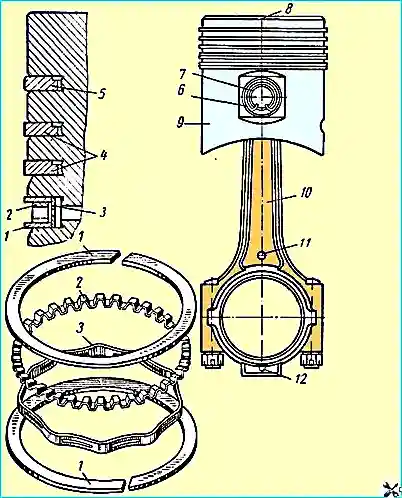
Piston rings are installed four on each piston: three compression rings and one oil scraper ring.
The two upper compression rings are chrome-plated along the outer cylindrical surface.
The outer surface of the lower compression ring is conical; the larger base of the cone faces downwards.
The compression rings are installed so that the recess on the inner cylindrical surface of the rings faces upwards, as shown in Fig. 1.
The oil scraper ring is composed of two flat steel rings and two expanders - axial and radial.
When installing the piston in the engine, the flat ring disks 1 must be installed so that their locks are located at an angle of 180 ° relative to each other, and the locks of the axial 2 and radial 3 expanders - at an angle of 90 ° to the locks of the disks (each).
To remove or install piston rings, you must use a special tool.
The dimensions of the piston rings and the grooves in the piston, as well as the gaps between them and the gap in the lock are given in Table 2.
To increase the service life, the piston rings in a free state have a complex shape, as a result of which, after installing the ring in the cylinder, the most favorable distribution of ring pressure on the liner wall is ensured.
When installing the rings on the piston, their joints (locks) should be installed at an angle of 90° to each other.
connecting rods are steel, I-section. In the lower head of the connecting rod, thin-walled steel-aluminum liners with a thickness of 2-0.16 mm are installed.
A rolled bronze bushing is pressed into the upper head of the connecting rod.
The liners are manufactured with high precision, are completely interchangeable and do not require scraping, filing of joints or installation of gaskets during installation.
These operations are not allowed for thin-walled liners.
In a new engine, the diametrical clearance in the connection between the crankshaft connecting rod journal and the connecting rod with liners in assembly is 0.032-0.076 mm.
When installing a piston assembly with connecting rod arrow 8 on the piston bottom must always face the front end of the crankshaft.
In the piston with connecting rod assembly intended for the left cylinder group, mark 11 on the connecting rod rod and arrow 8 on the piston must face the same direction, and in the set for the right cylinder group - in different directions.
Tighten the connecting rod bolt nuts with a torque wrench to a tightening torque of 7-8 kgfm.
After tightening the nut, carefully cotter pin it.
If the hole in the bolt and the slot in the nut do not match at the specified tightening torque, an additional turn of the nut is allowed until the hole matches the nearest slot, while the tightening torque should not exceed 11.5 kgfm.
Check and tighten the connecting rod bolt nuts each time the oil pan is removed.
The difference in weight of the piston and connecting rod assemblies must not exceed 16 g.
Table 1
Group (I):
- - pin diameter - 28.0000-27.9975 mm;
- - piston hole diameter - 27.9950—27.9925 mm;
- - connecting rod small head hole diameter - 28.0070—28.0045 mm;
- - marking color - blue
Group (II):
- - pin diameter - 27.9975—27.9950 mm;
- - piston hole diameter - 27.9925—27.9900 mm;
- - connecting rod small head hole diameter - 28.0045—28.0020 mm;
- - marking color - red
Group (III):
- - pin diameter - 27.9950—27.9925 mm;
- - piston hole diameter - 27.9900 - 27.9875 mm;
- - connecting rod small head hole diameter - 28.0020—27.9995 mm;
- - marking color - white
Group (IV):
- - pin diameter - 27.9925—27.9900 mm;
- - piston hole diameter - 27.9875—27.9850 mm;
- - connecting rod small head hole diameter - 27.9995—27.9970 mm;
- - marking color - black
Note. All measurements are taken at a temperature of 20° C.
Table 2 Rings
Ring height:
- - upper compression rings - 2-0.012 mm;
- - lower compression rings - 2-0.012 mm;
- - oil scraper ring - 5-0.012 mm;
Piston groove height:
- - upper compression rings - 2+0.070+0.050 mm;
- - lower compression rings - 2+0.070+0.050 mm
- - oil scraper ring - 5+0.050+0.025 mm;
Ring-to-piston clearance (in groove):
- - upper compression rings - 0.050 – 0.082 mm;
- - lower compression rings - 0.050 – 0.082 mm;
- - oil scraper ring - 0.025 – 0.062 mm
Ring lock clearance:
- - upper compression rings - 0.35 – 0.7 mm;
- - lower compression rings - 0.3 – 0.65 mm;
- - oil scraper ring - 0.9 – 1.5 mm
")

")
")
")
")
")
")
")