Power steering pump 1 with a reservoir is mounted on the engine and is driven through a pulley by a V-belt from a pulley located on the front end of the crankshaft
Pulley 1 of the pump is secured to shaft 6 with an expanding conical sleeve 30, a key and a nut.
The pump is of the vane type, double-acting, i.e. two complete suction cycles and two discharge cycles are completed per revolution of the pump shaft.
Rotor 9 of the pump has grooves in which blades 14 move.
The rotor is mounted on shaft 6 of the pump on splines; rotor fit on splines is loose.
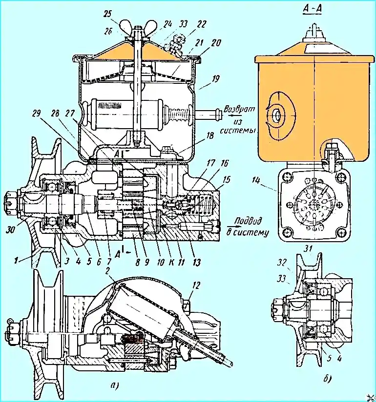
Fig. 1. Power steering pump: (a) - pump before modification; (b) - end of pump shaft after modification; 1 - pulley; 2 - mesh filter; 3 - pump housing; 4 - front bearing; 5 - oil seal; 6 - pump shaft; 7 - rear bearing; 8 - stator; 9 - rotor; 10 - distribution disk; 11 - pump cover; 12 - filter bypass valve; 13 - bypass valve; 14 - blade; 15 - adjusting linings; 16 - safety valve seat; 17 - safety valve; 18 - manifold; 19 - reservoir; 20 - pump cover gasket; 21 - filler mesh filter; 22 - breather; 23 - reservoir cover; 24 - washer; 25 - wing nut; 26 and 27 O-rings; 28 - manifold gasket; 29 - reservoir sealing gasket; 30 - conical bushing; 31 - bearing retaining ring; 32 - gland retaining ring; 33 - gland bushing
The position of the stator 8 relative to the pump housing 3 must be such that the direction of the arrow on the stator coincides with the direction of rotation of the pump shaft.
The pump blades must move in the rotor slots without jamming.
When the pump shaft rotates, the blades are pressed against the curvilinear surface of the stator under the action of centrifugal force and oil pressure.
In the suction cavities, oil gets into the space between the blades, and then, when the rotor rotates, is displaced into the discharge cavities.
The end surfaces of the housing and the distribution disk are carefully ground.
The presence of nicks, burrs, etc. on them, as well as on the rotor, stator and blades. unacceptable.
The pump has a reservoir 19 for oil, closed by a cover 23, which is tightened with a wing nut 25.
Under the wing nut there is a washer 24 and a rubber ring 26, which, together with a rubber gasket 20, seal the internal cavity of the reservoir.
A breather 22 is screwed into the reservoir cover to limit the pressure inside the reservoir.
All oil returning from the power steering to the pump passes through a mesh filter 2 located inside the reservoir.
In case of filter clogging, a bypass valve 12 is provided.
In addition, a filling mesh filter 21 is installed in the reservoir.
The pump has two valves located in the cover 11 of the pump.
Safety valve 17, located inside the bypass valve 12, limits the oil pressure in the system, opening at a pressure of 65-70 kg/cm 2.
The bypass valve limits the amount of oil supplied by the pump to the hydraulic booster when the engine crankshaft speed increases.
The bypass valve operates as follows.
The valve seat is connected on one side to the pump discharge cavity, and on the other - to the discharge line of the hydraulic booster system, which, in turn, is connected to the pump discharge cavity by a calibrated hole.
With an increase in the oil supply to the hydraulic booster system (as a result of an increase in the engine crankshaft speed), the pressure difference in the pump discharge cavity and the system discharge line increases due to the resistance of the hole K and, consequently, the pressure difference at the ends of the bypass valve.
At a certain pressure difference, the force tending to move the valve to the right increases so much that the spring is compressed and the valve, moving, communicates the discharge cavity with the tank.
Thus, further increase in oil supply to the system almost stops.
To prevent noise and increased wear of the pump at high engine crankshaft speeds, the oil that is bypassed by valve 13 is forcibly directed back into the cavity of the pump housing and into the suction channels.
For this purpose, manifold 18 is used, in which the internal channel communicating with the cavity of the bypass valve has a small cross-section.
This leads to a sharp increase in the flow rate of the bypassed oil into the suction cavity of the housing and creates a slight increase in pressure at the suction.
The radiator is predesigned to cool the oil in the power steering system.
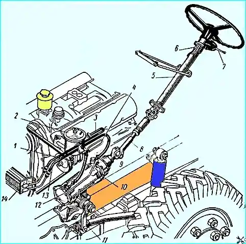
Tubular radiator 14 (see Fig. 2) is installed above the engine lubrication system oil radiator.
Oil from the steering gear to the radiator and from the radiator to the pump is supplied by rubber hoses secured with clamps.
")

")
")
")
")
")
")
")