During operation, it is necessary to regularly, at the times specified in the lubrication chart, check the oil level in the power steering system and flush the pump filters
The tightness of the connections and hoses of the power steering system should be checked daily.
The pump belt tension should also be checked daily.
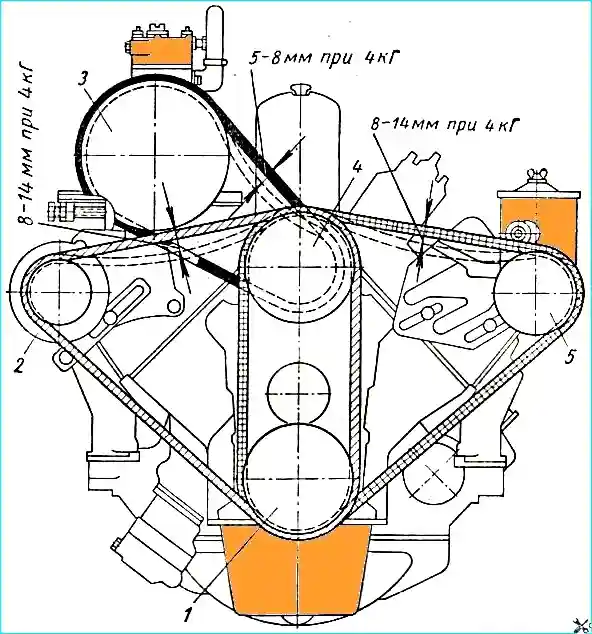
Diagram for checking the tension of drive belts: 1 - crankshaft pulley; 2 - generator pulley; 3 - compressor pulley; 4 - water pump pulley and fan pulley; 5 - Power steering pump pulley
The belt is tensioned by moving the power steering pump.
With normal tension, the belt deflection between the fan pulley and the power steering pump under a force of 4 kg should be within 8-14 mm (see Fig. 1).
Only clean, filtered oil specified in the lubrication chart should be used for the power steering system.
Oil should be added through a funnel with a double mesh and a filler filter installed in the power steering pump reservoir.
Using contaminated oil causes rapid wear of the pump and power steering parts.
When checking the oil level in the power steering system, which should be done at each maintenance, the front wheels of the car should be installed straight.
Before removing the cover the reservoir for checking the oil level, adding or changing it, the lid must be thoroughly cleaned of dirt and washed with gasoline.
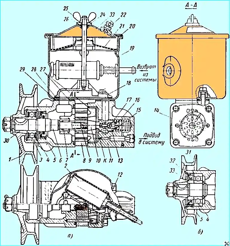
Power steering pump: (a) - pump before change; (b) - end of pump shaft after change; 1 - pulley; 2 - mesh filter; 3 - pump body; 4 - front bearing; 5 - oil seal; 6 - pump shaft; 7 - rear bearing; 8 - stator; 9 - rotor; 10 - distribution disk; 11 - pump cover; 12 - filter bypass valve; 13 - bypass valve; 14 - blade; 15 - adjusting linings; 16 - safety valve seat; 17 - safety valve; 18 - manifold; 19 - tank; 20 - pump cover gasket; 21 - filler mesh filter; 22 - breather; 23 - tank cover; 24 - washer; 25 - wing nut; 26 and 27 O-rings; 28 - manifold gasket; 29 - tank sealing gasket; 30 - conical bushing; 31 - bearing retaining ring; 32 - oil seal retaining ring; 33 - oil seal bushing
The oil should be added with the engine idling until oil appears above the mesh of the filler filter 21 (see Fig. 2). Full coverage of the mesh is not required.
During TO-2, both power steering pump filters must be washed in gasoline.
In case of significant clogging of the filters with resinous deposits, additional washing of the filters should be done with a solvent used when painting the car.
During maintenance, it is necessary to check the fastening of the steering gear housing to the frame, the steering column to the cab bracket, the steering wheel on the steering shaft, the tightening of the pitman arm, the tightening of the lock nut of the adjusting screw and the nuts of the driveshaft.
The tightening torque of the pitman arm nut should be 25-30 kgm, the lock nut of the adjusting screw 4-4.5 kgm, the nuts of the driveshaft wedges 1.4-1.7 kgm.
When installing hoses, do not twist them or make sharp bends.
Steering Gear Oil Change
When changing the oil, disconnect the vehicle's longitudinal tie rod and open the power steering pump reservoir cap.
To drain the oil, do the following:
- 1) turn the steering wheel all the way to the left;
- 2) open the drain hole by unscrewing the plug with the magnet from the steering gear housing.
The oil drain is complete when oil stops leaking from the drain hole of the steering gear housing.
After draining, flush the power steering system, which requires:
- - remove any remaining contaminated oil from the power steering pump reservoir; the presence of residues of wiping material in the tank is unacceptable;
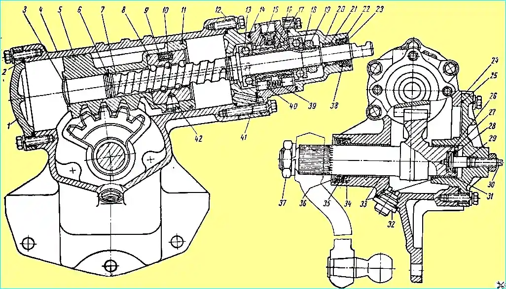
Steering gear: 1 - lower cover; 2, 14, 25, 29 and 41 - sealing rings; 3 - plug; 4 - steering gear housing; 5 - rack piston; 6 - split sealing ring; 7 - steering screw; 8 - ball nut; 9 - groove; 10 - ball; 11 - split piston rings; 12 - intermediate cover; 13 - thrust ball bearing; 15 - ball valve; 15 - spool valve; 17 - control valve body; 18 - spring washer; 19 - adjusting nut; 20 - top cover; 21 - needle bearing 22 and 35 - oil seal thrust rings; 23 - outer sealing cuff; 24 - side cover; 26 - thrust washer; 27 - adjusting washer; 28 - retaining ring; 30 - adjusting screw; 31 - pitman arm shaft; 32 - drain plug with magnet; 33 - pitman arm shaft bushings; 34 and 38 - oil seals; 36 - rubber cuff; 37 - pitman arm shaft nut; 39 - reaction spring; 40 - reaction plunger; 42 - set screw
- - wash washer 24 (see Fig. 2), rubber sealing ring 26 of the pump cover and drain plug 32 (see Fig. 3) with the magnet of the steering gear housing, cleaning them from dirt; remove and wash the pump filter screens and put them back in place;
- - pour 1 liter of fresh oil into the pump tank through a funnel with a double screen and drain this oil through the drain hole of the steering gear housing, while turning the steering wheel from lock to lock.
To fill in fresh oil, you need to:
- 1. Screw the plug with the magnet into the drain hole of the steering gear housing.
- 2. With the steering wheel turned all the way to the left, pour fresh oil into the pump reservoir until oil appears above the mesh of the filler filter.
Then, turning the steering wheel from lock to lock and without applying force to the stops, add oil until at least 2.5 liters of oil are poured into the system.
Start the engine, then add fresh oil and, with the engine idling, turn the steering wheel from lock to lock, holding it briefly on the stops for 2-3 seconds with a force of about 10 kg and adding oil as needed until it appears above the mesh (complete coverage of the mesh is not required).
Oil filling is considered complete when air stops escaping from the system in the form of bubbles through the oil in the pump reservoir.
- 3. Stop the engine, install the tank cap with the sealing gasket, rubber sealing ring, cap mounting studs and washer and secure with the wing nut. Tighten the wing nut by hand.
If oil leaks from under the tank cap, check that the cap gasket is installed correctly and replace it if damaged.
- 4. Connect the longitudinal rod and lubricate the joint.
Driving with a non-working power steering
If the power steering fails to operate due to damage to the pump or power steering, destruction of the hose or pump drive belt, or engine stalling, the steering gear can only be used for a short time until the fault is corrected.
Long-term operation of the vehicle with a non-working power steering leads to rapid wear of the steering mechanism or its failure.
If the power steering pump hoses rupture, you should:
- 1) connect the pump discharge hole to the branch pipe on the pump reservoir;
- 2) close the discharge and return holes on the power steering with wooden plugs or in another way that ensures protection against dirt or foreign bodies;
- 3) add oil to the pump reservoir to the level specified above; it is allowed to fill with the oil used for the engine, replacing it at the base;
- 4) drive to the base with the engine running at the lowest possible crankshaft speed, monitoring the oil temperature in the tank.
If the oil heats up, stop and let the oil cool.
Steering rods
The steering drive consists of longitudinal and transverse steering rods.
The longitudinal steering rod is tubular, with adjustable ball joints.
Each joint has a spring and two spherical crackers, between which the ball head of the pin is located, clamped by an adjusting plug.
The longitudinal steering rod connects the ball pins of the lower end of the steering knuckle with the lever of the housing of the left ball joint of the front bridge.
It is necessary that the rod with a shorter arm along the bend is put on the ball pin of the knuckle.
When assembling the hinge, the adjusting plug is tightened to the stop, and then released to the first possible position for cotter pinning, but not less than ¼ turn, and cotter pinned.
It should be remembered that complete elimination of gaps in the hinges is not allowed, as this can lead to breakage of the ball pin or rod.
To retain grease in the hinges and protect them from dirt The grooves for the ball pins in the tie rod head are covered with felt pads.
The transverse steering rod has right-hand threads with different pitches at the ends for screwing in heads with ball joints, with the help of which it is possible to change the length of the rod and thereby adjust the toe-in of the wheels.
The heads of the joints are made with upper and lower liners and a spring pressing the liners.
The joints do not require adjustment.
During assembly, it is necessary to ensure that the ball pins can be turned by hand without jamming.
All fasteners should be checked and tightened daily, the condition of the hinge joints of the longitudinal and transverse steering rods should be checked, and if necessary, the joint clearance should be adjusted and the steering tie rods should be lubricated according to the lubrication chart.
")

")
")
")
")
")
")
")