It is necessary to regularly add grease to the axles and replace it as indicated in the lubrication chart
Oil must be poured into the crankcases of all axles of the vehicle through the filler (inspection) hole located in the upper wall of the gearbox housing, closed with plug 29, until oil leaks from the open inspection hole.
You can add oil to the front axle crankcase, in addition to the filler hole, through the control hole located in the axle crankcase cover.
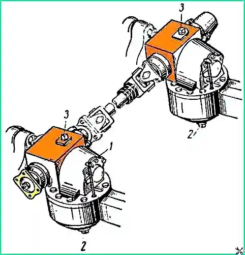
Check the oil level in the rear and middle axles during operation using a special level indicator 1 (Fig. 1) available in the tool kit.
To check the oil level in the rear and middle axles, you need to unscrew the bolt shown in Fig. 1, attach the gearbox to the axle housing and insert the oil level indicator into the bolt hole until it stops against the gearbox housing flange.
The correct oil level is indicated by a mark on the oil level indicator rod.
If the oil level drops below the mark, it is necessary to add oil to the crankcase to the level of the control plug.
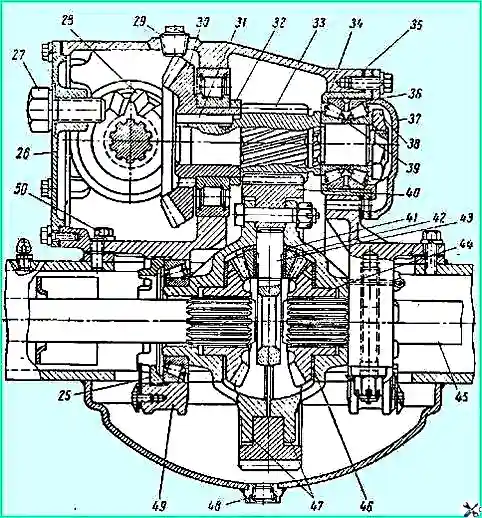
Middle and rear axle gearbox (front view): 25 - differential bearing nut; 26 cover; 27 - bolt puller; 28 - drive bevel gear; 29 - filler plug; 30 - driven bevel gear; 31 - key; 32 - spacer ring; 33 - drive cylindrical gear; 34 - bearing seat; 35 - adjusting shims; 36 - double-row bearing; 37 - bearing cover; 38 - nut of the bearing of the drive cylindrical gear; 39 - adjusting ring; 40 - driven cylindrical gear; 41 - satellite support washer; 42 - satellite; 43 - differential cross; 44 - axle gear; 45 - axle shaft; 46 - axle gear support washer; 47 - differential cups; 48 - drain plug; 49 - gear housing; 50 - gearbox housing mounting bolt
To drain used oil from the front axle housing, there is a drain hole 48 (Figure 2), located in the lower part of the axle housing.
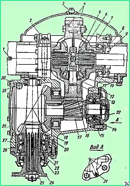
Front axle gearbox with differential: 1 - breather; 2 - nut securing the differential bearing cover; 3 - control hole plug; 4 - differential cups; 5 - axle gear; 6 - support washer; 7 - bearing cover; 8 - nut stopper; 9 - adjusting nut; 10 - gearbox housing; 11 - satellite; 12 - satellite support washer; 13 - differential crosspiece; 14 - bearing seat; 15 - adjusting shims; 16 - driven cylindrical gear; 17 - drive cylindrical gear; 17 - driven bevel gear; 19 - drive bevel gear; 20 - cup of bearings; 21 - bearing cover; 22 - oil washer; 23 - oil seal; 24 - flange; 25 - drive bevel gear shaft; 26 - adjusting shims; 27 - adjusting washers; 28 - cover; 29 - cylindrical roller bearing; 30 - drain plug; 31 - blind plug; 32 - cover
The drain holes for the rear and middle axle housings are located at the bottom of the housing covers.
In addition, there are additional drain holes for removing residual oil from the gearbox housings: a hole with plug 30 (Figure 3), located in the lower wall of the front axle gear housing, and holes with plugs 36 (Figure 4), made in the front walls gear housings of the rear and middle axles.
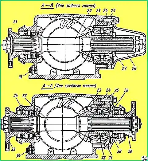
Figure 4. Gearbox of the middle and rear axle: 21, 29, 33 - flanges for fastening cardan shafts; 22 - through shaft; 23 - drive bevel gear; 24 - adjusting shims; 25 - cup of bearings; 26 - spacer sleeve; 27 - washer; 28 - bearing cover; 30 oil removal washer; 31 - tapered roller bearing; 32 - for bearing lubrication; 34 - oil seal; 35 - oil channel; 36 - drain plug
Drain the used oil after preheating the unit through all available drains holes.
The control holes must be open.
If necessary, add grease to the steering knuckle housing for the king pin bearings and the front drive axle axle joint.
It is necessary to fill the lubricant in a heated state through grease nipples 17 (Figure 5), located in the upper lining of the right steering knuckle housing and in the swing arm mounted on the left steering knuckle housing; you need to fill it until the lubricant begins to come out through the control hole located at the bottom of the ball joint.
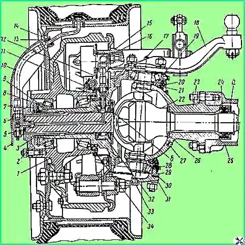
Figure 5. Drive to the drive wheels of the front axle: 1 - hub; 2 - flange; 3 - axle; 4 - protective casing of the air supply tube; 5 - channel for air supply; 6 - tire tap; 7 - external nut; 8 - internal nut; 9 - lock washer; 10 - air supply hose to the tire; 11 - external oil seal; 12- air supply hose to the air supply head. 13 - oil seal; 14 - nut; 15 - brake bracket; 10 - square; 17 - oiler; 18 - rotary lever; 19 - adjusting shims; 20 - steering knuckle housing oil seal; 21 - oil seal; 22 - axle shaft assembled with a fist; 23 - ball joint; 24 - axle shaft seal; 25 - crankcase; 26 - support washer; 27 - control hole plug; 28 - plug; 29 - steering knuckle housing; 30 - lower adjusting shims; 31 - lower lining of the steering knuckle; 32 - air supply head; 33 - plug; 34 - inner hub seal
Plug 27, which closes this hole, must first be unscrewed.
When changing the lubricant, all parts of the steering knuckle and the axle shaft joint must be washed.
Fresh lubricant is placed directly inside the ball joint, in the pin bearings and in the axle joint.
The wheel hub must also be washed when changing.
When adding fresh grease, the bearings must be thoroughly lubricated.
Tightening torques for bolted connections in kgm
- Nuts of bolts securing differential cups and driven spur gear 12—14
- Nuts of studs securing differential bearing caps 17-19
- Studs for securing differential bearing caps (when installed in the gearbox housing) 22-25
- Bolts for fastening the gearbox roller bearing covers - 6-8
- Bolts securing the gearbox to the axle housing - 9-11
- Nuts of the studs securing the axle shafts of the rear and middle axles, flanges of the axle shafts of the front drive axle to the wheel hubs 7-9
- Nuts of the studs securing the steering knuckle lever to the body and the studs securing the ball joint to the front axle housing ... 16-18
- Nuts of the studs securing the axles of the front, rear and middle axles 5.5-6
- Nuts securing the shaft flanges of the drive bevel gear 20-25
- Nut securing the shaft bearing of the drive spur gear 35-40
- Wheel hub bearing locknut 12-15
- Tie rod ball pin fastening nut 23-27
Axle breathers should be regularly cleaned of dirt.
The breathers for communicating the internal cavity of the axle housing with the atmosphere are located in the upper walls of the axle beams: on the front axle - to the left (downstream) of the gearbox, on the rear and middle axles to the right (downstream) of the gearbox.
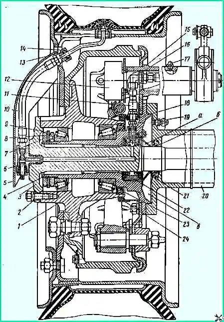
Fig. 6. Hub of the middle and rear axle (front view): 1 - hub; 2 - expansion sleeve; 3 - right axle shaft; 4 - axle; 5 - protective casing of the air supply tube to the wheel tire; 6 - tire tap; 7 - external bearing nut; 8 - inner nut of bearings; 9 - lock washer; 10 - hose supplying air to the tire; 11 - air supply hose to the air supply head; 12 - expansion fist; 13 - oil seal; 14 - nut; 15 - brake bracket; 16 - square; 17 - oiler; 18 - hose tip seal; 19 - breather; 20 - crankcase; 21 - axle shaft seal; 22 - air supply head; 23 - inner hub seal; 24 - outer hub seal
In addition, there are additional breathers 19 (see Figure 6) for air release in the event of a malfunction of the oil seals of the heads 22 for supplying air to the tires.
These breathers are located: on the front axle in the steering knuckle housings, above the steering linkage arms, on the rear and middle axles - in the end flanges of the axle housings.
The appearance of grease from the holes of these breathers indicates an air leak from the tire pressure control system.
The cause of the leak must be found and eliminated. If there is a leak, it is necessary to replace the air supply heads to the tires.
You should check for oil leaks and through seals and flange connections.
Faulty oil seals and gaskets must be replaced, and bolts and nuts of flange connections must be tightened in a timely manner.
It is necessary to constantly monitor the tightness of bolt connections, especially the gearbox mounting bolts, the nuts securing the axle shafts to the wheel hubs, the nuts securing the ball joint to the axle housing flange, and the nuts securing the steering knuckle arm.
We must remember that two of the twelve gearbox mounting bolts are located inside the gearbox housing. In order to tighten them, you must first remove the cover 26 of the gearbox housing.
Whenever you remove the brake drums, you need to tighten the axle nuts.
When assembling bridges, the following requirements must be met to ensure tightness when a vehicle crosses fords:
- 1) all flange connections, both those with sealing gaskets and those without gaskets, must be lubricated with sealing paste during assembly;
- 2) before installation, steel adjusting shims must be washed and lubricated with spindle oil (GOST 1642-50) or other similar liquid oil;
- 3) thin shims should be installed on both sides of the shim set;
- 4) control plug 27 of the drain hole (see Figure 5) of the ball joint must be lubricated with UN-25 paste before reinstalling.
The axle shafts must be removed and inserted very carefully so as not to damage the seals and rubber seals of the air supply head to the wheel, located inside the axles.
Before installing the axle shafts of the rear and middle axles, the journals of the axle shafts under the oil seals and under the air supply heads must be lubricated with the grease specified in the lubrication chart for wheel hub bearings.
The thickness of the lubricant layer is 1-1.5 mm.
The axle shafts of the front drive axle must have lubricated journals for oil seals.
Before reinstalling the steering knuckle axle of the front drive axle and the crankcase axles of the rear and middle axles, the working surfaces of the cuffs and the surfaces of the centering holes of the air supply heads must be lubricated with a thin layer of the same lubricant.
The internal cavity of the air supply head must be filled with lubricant; in this case, the hole for the fitting must be free of grease.
For the front drive axle, in addition, the journals under the air supply head and under the bronze bushing at the knuckles of the axle shaft joints must be lubricated.
The internal cavity “a” (see figure) of the axle shaft seal races and the space “b” between the air supply head and the support ring must also be filled with lubricant.
For the rear and middle axles, the following must be filled with the specified lubricant: space “a” (see Figure 6) between the air supply head and the oil seal protective sleeve, space “b” between the axle shaft oil seal and the crankcase support flange, as well as cavity “c” » between the flanges of the axle and the axle housing.
When installing the trunnions in place, it is necessary to ensure the correct position of the air supply holes in the journals of the trunnions.
The hole should be directed:
- a) for the front axle - up and back, behind the second axle mounting pin from the vertical;
- b) for the middle bridge - up and back, behind the first pin from the vertical;
- c) for the rear axle - up and forward, behind the first stud from the vertical.
Assembling and disassembling the hinges of the axle shafts of the front drive axle requires some effort when installing and removing the drive ball and requires special skill, so disassembling the hinge should only be done if absolutely necessary and this should be done in a workshop.
When disassembling, you should mark with chalk or paint the relative position of the driving and driven forks and driving balls, and when assembling, install all the parts in the same relative position that they had before disassembly.
To facilitate the removal of the axle shafts of the rear and middle axles and the removal of the flange of the hinge knuckle of the axle shaft of the front drive axle, puller bolts are used, wrapped in the flanges of the axle shafts and locked with lock nuts.
For the same purpose, holes with M12 threads (pitch 1.75 mm) are made in the flanges of the following parts: steering knuckle axle; ball joint of the steering knuckle; beam axle of the rear and middle axles; bearing housing for the drive bevel gear of the gearbox; bearing seat of the driven bevel gear of the gearbox.
As a puller for these parts, you can use any fastening bolt with M12 thread (1.75 mm pitch) used for fastening bridge parts.
Removing the top cap of the kingpin bearings mounted on the steering knuckle housing is made easier by tapping it with a hammer from the side, on an untreated surface.
")

")
")
")
")
")
")
")