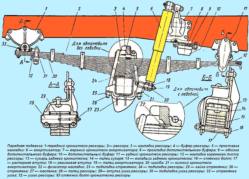
The front suspension consists of two longitudinal semi-elliptical springs and two telescopic shock absorbers
The springs of 2 cars equipped with a winch have 17 sheets, and the springs of cars without a winch have 15 sheets.
The front ends of the springs are fixed to the frame brackets 1 with detachable lugs 32 and pins 28.
The eye is attached to the spring through the lining 30 with two bolts, a stepladder; the spring is kept from displacement by special protrusions on the root sheet and lining.
The bushing 29 made of heat-treated ductile iron is pressed into the eye.

The rear ends of the front springs rest on crackers 13 pressed onto brackets 11.
Inserts 15 are installed on the fingers 14 of the crackers, protecting the walls of the bracket from wear.
The inserts are fixed with tie bolts 16. Sleeves 17 are installed on the tie bolts.
A slip 12 is riveted on the sliding end of the root sheet, protecting it from wear.
The friction parts are heat treated to increase their service life.
Each spring is attached to the front axle with stepladders 26 in the middle part.
Rubber buffers 4 soften the impact of the springs on the frame; buffers 10 reduce the forward steering of the axle when braking.

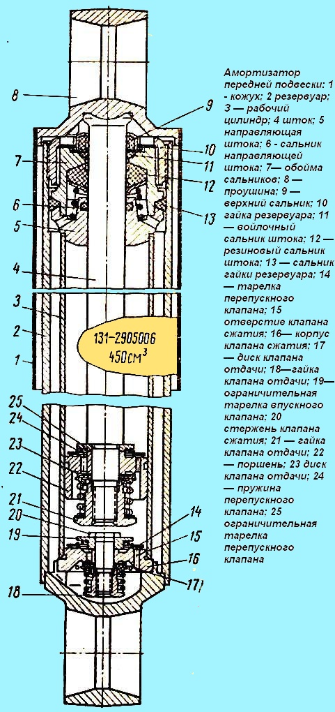
The shock absorber (Fig. 2) is attached to the frame bracket by the upper eye 8, and to the front axle by the lower eye.
Shock absorbers are designed to dampen vibrations that occur when the car moves over uneven roads.
This improves the vehicle's ride and handling, and extends the life of the springs.
The principle of operation of hydraulic shock absorbers is that as a result of the relative movements of the sprung and unsprung parts of the car, fluid flows from one cavity of the shock absorber to another through small holes, as a result of which the shock absorber provides resistance that dampens the vibrations of the springs.
The greatest resistance created by the shock absorber occurs when it is stretched (recoil), when the sprung part of the car moves away from its unsprung part (wheels with axles).

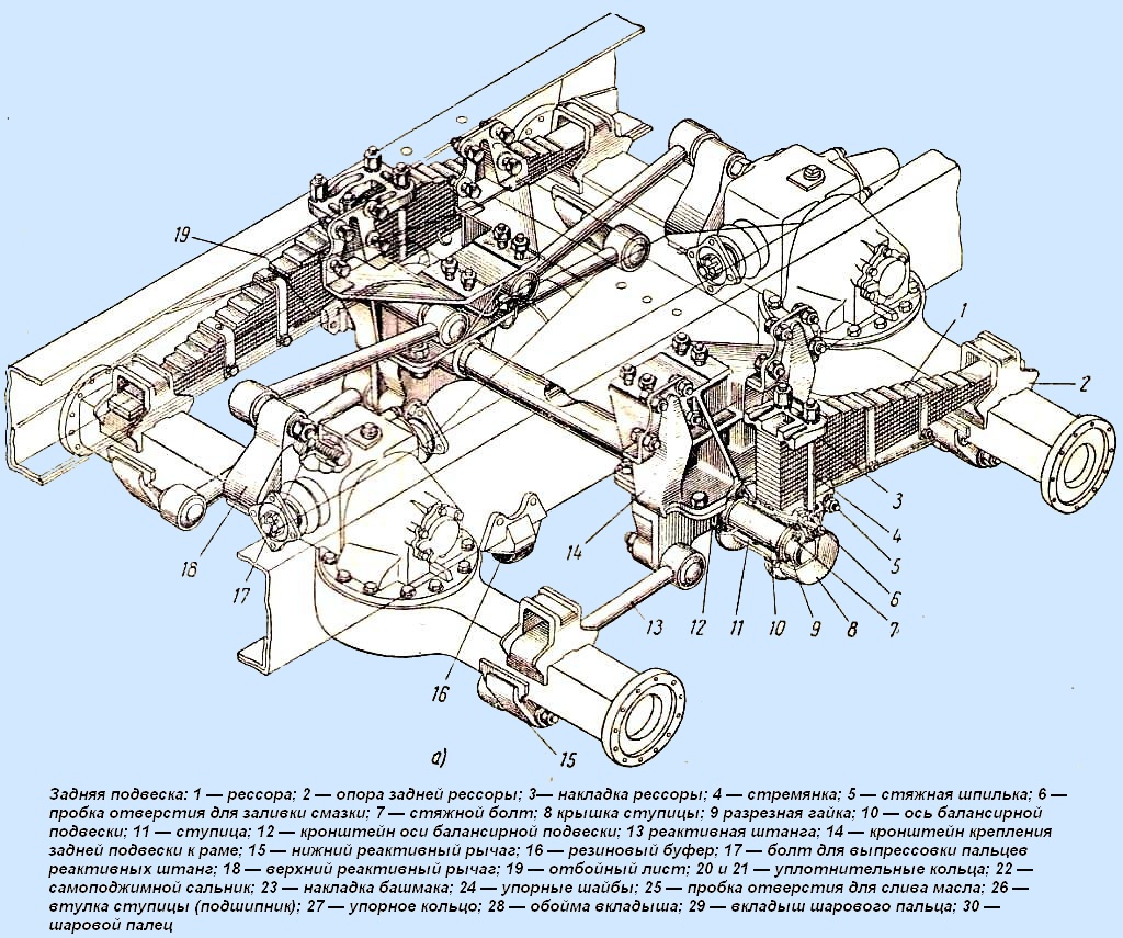
Rear suspension of the middle and rear axles of the balancing type, on two longitudinal semi-elliptical springs.
Each spring is attached with the help of stepladders 4 (Fig. 3, a) to the hub 11 of the axis of the balancing device.
The ends of the springs enter the holes of the supports 2 welded to the axles. When the springs deflect, their ends slide in the holes of the supports.
Rubber buffers 16 are installed on the spars to limit the upward movement of the bridges and soften their impacts on the frame.
Pushing forces and reaction moments are transmitted to the frame by six reaction rods 13 (three for each axle).
The side forces are transferred from the axles to the frame through the springs.
The hinges of the jet rods are non-separable, they consist of ball pins 30, a clip 28 and an insert 29 made of a woven tape impregnated with a special compound.
Hinge cages are pressed into torque rod heads.

The balancing device consists of an axle 10, pressed into brackets 12, and hubs 11.
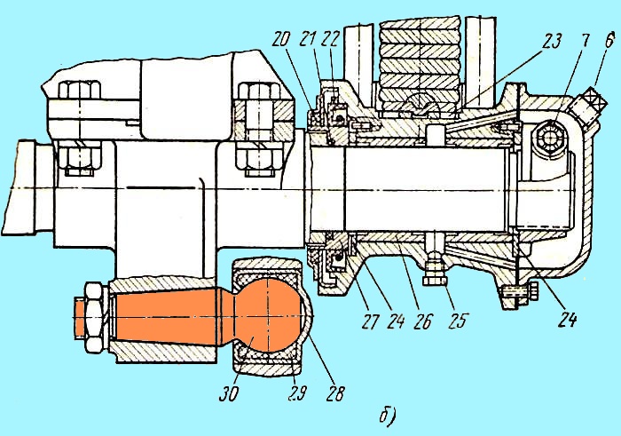
The ends of the axle are hardened, and bushings 26 (Fig. 3, b) made of anti-friction material are pressed into the hubs.
To prevent the inflow of grease and protect against dirt, self-clamping seals 22 and sealing rings 20 and 21 are installed in the hubs.
The hubs are fixed on the axle with split nuts 9, tightened with bolts 7. The nuts of the coupling bolts are self-locking.
In the cover 8 of the hub there is a plug 6 for filling oil, and in the hub there is a plug 25 for draining it.
The entire rear suspension is attached to the frame using brackets 14.
Care of the suspension consists in lubricating the spring pins, springs and periodically changing the lubricant in the hubs of the balancing suspension, checking the fastening of the springs, shock absorbers and torque rods, checking and adjusting the axial clearances of the hubs of the balancing suspension.
Lubrication is a prerequisite for reliable and long-term operation of the springs. Corrosion (rusting) of the sheets can reduce the life of the springs.
During repair work, it is necessary to overhaul and lubricate all springs of the car.
When overhauling the springs, it is necessary to remove old grease and dirt, as well as traces of corrosion, and then lubricate the rubbing surfaces of the springs with a special graphite grease.
About at the same time, the ears and pins of the front springs should be washed and lubricated.
When the ends of the main sheets of the rear springs are worn, it is recommended to swap the first and third sheets.
Lubrication of the fingers of the front springs is carried out through oilers 27 until fresh grease appears in the gaps between the ears and brackets.
To drain the lubricant from the hub of the balancing suspension, it is necessary to remove the cover 8 (Fig. 3) and unscrew the plug 25. Oil should be poured into the hubs up to the level of the filling holes closed with plugs 6.
Lubrication intervals and grades of lubricants are indicated in the lubrication chart.
The tightness of the following connections should also be periodically checked: nuts of the front and rear springs ladders; coupling bolts 33 (see Fig. 1) of the fingers of the front springs; nuts of ladders 31 lugs of front springs; finger nuts 19 shock absorbers; tie rods 5 (fig. 3) cheeks of the hubs of the rear springs; bolts for fastening brackets 14 of the rear suspension to the frame; bolts for fastening the brackets 12 of the axis of the balancing suspension to the brackets 14; torque rod pin nuts.
Tightening torques for suspension screw connections in kgm
Nuts for the stepladders of the front and rear springs 25—30
Front spring pin coupling bolts 5.5-6
Nuts for the stepladders of the ears of the front springs - until the spring washers are compressed, no more
Shock absorber pins on the side of the cone 12-14
Shock absorber pin nuts on shock absorber side 5.5-6
The nuts of the tie rods of the cheeks of the hubs of the rear springs - until the gaps between the cheeks and the spring are eliminated
The bolts of the rear suspension brackets to the frame 8—9
Bolts for fastening the brackets of the balance suspension axle to the brackets of the frame 30, not less than
Tan tine nuts 35-40
Coupling bolts for slotted nuts of balancer suspension hubs - 8—10
At the second TO-2, simultaneously with changing the lubricant, it is necessary to remove the hubs of the balancing suspension from the axle, wash them and the ends of the axle, check the condition of the oil seal 22 (Fig. 3), felt ring 20 and thrust ring 27.
Worn parts should be replaced.
Operating a vehicle with a worn hub seal leads to lubricant leakage and premature wear of the axle and bushings due to dirt entering the hub.
When installing the hubs on the axle, it is necessary to tighten the coupling bolts 7 split nuts 9.
After assembly, the hubs should rotate freely on the axle and have no appreciable axial clearance.
To remove the upper torque rods, there are special bolts 17 in the side covers of the axle gearboxes, when unscrewing which the fingers are pressed out of their sockets.
The wear parts of the rear brackets of the front springs [inserts 15 (Fig. 1) and crackers 13] are replaceable and, if necessary, can be replaced with new ones during repair work.
Repair of worn journals and bushings of the balancing suspension axle should be carried out by replacing the bushings with repair ones. Repair instructions for the axle and bushings are included with the set of repair bushings.
During operation, no special adjustment of the shock absorbers is required. Periodically, you should check the reliability of the fastening of the shock absorbers on the car and the correct operation.
If traces of oil leakage appear on the shock absorber, tighten the nut 10 (see Fig. 2) of the tank, for which it is necessary to remove the shock absorber from the car.
In the event of a fluid leak that cannot be eliminated by tightening the reservoir nut, the stem seal must be replaced.
When replacing the stem seals, keep in mind that the seal 12 has a “Bottom” mark indicating the correct position of the seal when installing it.
This position ensures proper operation of the oil seal grooves.
The shock absorbers should only be filled with shock absorber fluid in accordance with the lubrication map.
The fluid is changed with the shock absorber removed from the car.
Before pouring, put the shock absorber vertically, fix the lower lug, raise the rod to the upper position, unscrew the reservoir nut and remove the rod with the piston; prepare 0.45 l of liquid and fill working cylinder 3 to the top, drain the remaining liquid into reservoir 2 of the shock absorber; then you need to assemble the shock absorber and install it on the car.
When pouring liquid, it is necessary to ensure that dirt, sand, etc., do not get into the shock absorbers, which lead to rapid wear of parts and failure of the shock absorbers.
It is necessary to disassemble and assemble the shock absorber in workshops, in conditions that fully ensure cleanliness; without extreme necessity, the shock absorber should not be disassembled.


