The power take-off (Fig. 1) is reversible, serves to drive the winch and is installed on the flange of the gearbox hatch
The drive block 16 of the gears and the intermediate gear 13 are mounted on fixed axles 11 and 14 on roller bearings 17
Shaft 10 rotates on two ball bearings 8. Gear 9 slides along the splines of the shaft.
A flange 22 is installed at the shaft outlet, sealed with a cuff 23.
Installation of a flange on the shaft, if necessary, can be carried out both to transmit torque forward as the vehicle moves, and backward, by correspondingly rearranging shaft 10.
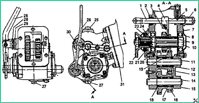
Power take-off: 1 - gear fork rod; 2 and 23 - cuffs; 3 - sealing ring; 4 - power plug; 5 - ball retainer; 6 - rod plug; 7 - rear bearing cover, 8 - ball bearing; 9 - gear wheel; 10 - main shaft; 11 - axis of the constant mesh gear; 12 - support washer; 13 - intermediate gear wheel of constant mesh; 14 - axis of the gear block; 15 - gearbox housing; 16 - gear block; 17 - roller bearing; 18 - support washer; 19 - spacer ring; 20 - bearing cover gasket; 21 - front bearing cover, 22 - flange; 24 - flange support washer; 25 - filler plug; 26 - power take-off lever; 27 - drain plug, 28 - nut; 29 lock nut; 30 - lever bracket; 31 – gasket
The gears are engaged by a fork 4, fixedly mounted on the rod 1. At the output of the rod there is a cuff 2.
All gears of the power take-off are spur-cut.
The power take-off is controlled through a hatch in the cab floor using the key S=46 from the driver's tool kit, used as an extension of the power take-off lever and inserted into the bushing on the lever
The gear of the drive block 16 of the power take-off is in constant engagement with the gear wheel of the reverse gearbox.
Incorrect installation of the power take-off increases the noise of gear pairs and leads to accelerated wear.
For proper installation, the stud nuts should be tightened evenly in a cross pattern, while simultaneously turning the shaft 10.
The sealing gasket 31 between the mating planes of the flanges of the gearbox and power take-off must be 0.3-0.4 mm thick (the gasket from under the gearbox hatch cover is used).
When the power take-off is installed correctly, shaft 10 rotates freely (without gears jamming) by hand force applied to the output end of the shaft.
Maintenance of the power take-off is the same as the gearbox.
After performing maintenance on the power take-off or replacing it, it is necessary to check that the power take-off lever is in the neutral position.
Failure to comply with this requirement may result in the winch cable breaking when starting the engine.
Design of power take-off from the transfer case (KOM-1)
A single-speed power take-off (Fig. 2) is installed on the top hatch of the transfer case.
This makes it possible to take power from the transmission to drive various special units used by the consumer when using the car chassis as a transport base.
Single-speed power take-off is designed for short-term operation.
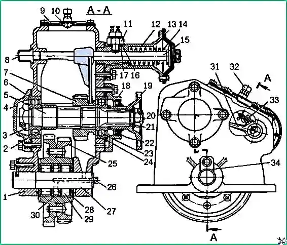
Power take-off (KOM-1): 1 - crankcase; 2 - spacer sleeve; 3 and 20 - nuts; 4 and 18 - bearing caps; 5 - driven shaft; 6 and 23 - ball bearings; 7 - carriage gear; 8 - plug, 9 - hatch cover; 10 - shield; 11 - switch; 12 - switching chamber; 13 - membrane; 14 - spring; 15 - rod, 16 - gasket; 17 - adjusting washer; 19 - flange; 21 - spring washer; 22 and 28 - support washers; 24 - retaining ring, 25 - constant mesh gear; 26 - plug; 27 - axis; 29 - roller bearing; 30 - spacer ring; 31 - fork; 32 - ventilation tube fitting; 33 - lock bolt; 34 - locking plate
The duration of continuous operation depends on the actual amount of power taken and is checked in each specific case by preliminary tests.
The parts of the single-speed power take-off are mounted in a cast iron crankcase 1 (see Fig. 2).
The gear block is mounted on a fixed axis 27 on two roller bearings 29, between which there is a spacer e ring 30.
The axle is pressed into the front and rear walls of the crankcase and locked with a plate.
On the axle at the ends of the hub of the gear block, support washers 28 are installed, which prevent wear of the support ends of the crankcase.
The axle has axial and radial holes for supplying oil from the crankcase to the roller bearings. The axial hole is closed from the outside with a conical plug 26.
When the power take-off is turned on, gear-carriage 7, movably mounted on the splines of shaft 5, engages with gear 25.
To prevent self-switching off, the secondary shaft has a slot-lock.
A spacer sleeve 2 is installed between the splined part of the shaft and the front bearing 6. The bearing and spacer sleeve are tightened with a nut 3.
The nut is locked by pressing the thin edge of the nut into the groove of shaft 5.
The shaft rotates on two ball bearings 6 and 23, the outer rings of which are installed in the housings of the crankcase, and the inner rings are pressed onto the shaft journals.
In the axial direction, the secondary shaft is fixed by bearing caps 4 and 18. A cuff is installed in the cap 18, protecting the box from dirt and oil leakage.
At the splined end of shaft 5 there is a flange 19 for fastening the propeller shaft. The flange is secured with nut 20, which is locked in the same way as nut 3.
The power take-off is switched on using a fork 31. The fork is fixedly fixed to the rod 15 with a bolt 33, which is secured with a wire.
There is a hole in the front wall of the crankcase through which rod 15 moves. This hole is closed with plug 8.
The upper hatch of the power take-off is closed with a cover.
There is a fitting 32 on the cover, connected by a rubber hose to a ventilation tube mounted on the rear wall of the cabin. The fitting is protected from direct oil ingress by shield 10.
Electro-pneumatic control is carried out by a button installed on the instrument panel in the cockpit.
The button opens and closes the electrical control circuit of the air valve actuator solenoid relay.
The relay is installed on the engine shield in the engine compartment above the front axle electromagnet activation relay.
When the power take-off is turned on by the switch, the relay is activated and closes the power supply circuit of the electromagnet.
The electromagnet core, moving downwards, presses on the air valve activation rod and opens it.
Air enters the switching chamber through the inlet valve and, acting on the membrane 13, moves the rod 15 connected to the power take-off fork.
On the body of the switching chamber there is a switch 11 installed to indicate that the power take-off is off.
When the rod moves, the switch contacts close and the red indicator lights up.
When the power take-off is turned off, the power supply circuit of the electromagnet is opened, the air valve closes, and the return spring of the membrane chamber moves the rod and fork to its original position.
The gear-carriage 7 disengages and the power take-off turns off, while the contacts of the warning light switch open and the warning light goes off.
Maintenance of the single-speed power take-off is the same as that of the transfer case.
Power take-off repair
Before removing the power take-off, you must first drain the oil from the gearbox housing and power take-off by unscrewing the two drain plugs.
Disconnect the cardan drive of the winch drive, unscrew the nuts securing the power take-off box on the flange of the crankcase hatch and manually remove the power take-off box from the studs of the gearbox hatch.
Removing the flange
Unscrew the flange mounting nut with a socket wrench and remove the washer.
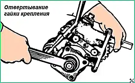
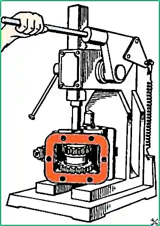
When unscrewing the nut, you must hold the shaft from turning using a copper or aluminum mandrel, inserting it between the gears of the box (Fig. 3).
Remove the shift lever by first undoing the pins with pliers and removing the axial and connecting pins with the fork rod.
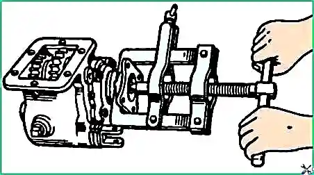
Install the 20P-7973 puller on the flange and use it to remove the flange from the shaft (Fig. 4).
Unscrew the bolts securing the covers, lightly tap the covers with a hammer and remove the covers and gaskets.
To remove the locking plate of the gear block axles, you need to unscrew the bolt securing the plates and remove the plate
Removing the gear block
Install the box on the press and press out (towards the end with the groove) the axle gear block (Fig. 5), remove the gear block from the crankcase, remove the thrust washers, remove two roller bearings and a spacer from the block.
Removal of gear 25 (see Fig. 2) of constant mesh is carried out in the same way as the gear block.
In this case, gear 7 must be disengaged from the constant mesh gear.
Removing the main shaft
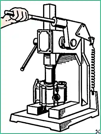
Install the box body on the press, press out (Fig. 6) the main shaft until the rings of one bearing come out of the box and remove the bearing and gear.
Press the second bearing from the main shaft using a puller mod. 20P-7973.
Using pliers, undo the locking bolt securing the power fork and unscrew it.
Then unscrew the locking plug and remove the spring and locking ball from the socket.
Then remove the rod, while simultaneously removing the gear shift fork from it.
The rod seal is removed from the socket only when it is replaced.
Power take-off parts
Repair requirements for the crankcase, gears, shafts and other parts of the power take-off are similar to the requirements for gearbox parts.
Assembling the power take-off
Parts prepared for assembly must be checked for size, washed in a degreasing solution and blown with compressed air.
If the main shaft bearing cuffs and rod cuffs are worn or damaged, they must be replaced with new ones.
Assembly of the power take-off is carried out in the reverse order of disassembly.
When installing the gear shift fork, it should be secured with a locking bolt and a cotter pin.
Installation and fastening of the rod clamp must be carried out after installing the gear shift gear on the main shaft.
The axial clearance of the main shaft is adjusted using shims 20 (see Fig. 1▲), reducing or increasing the number of shims located under the covers.
The bearings are adjusted correctly if the shaft rotates freely by hand (in the absence of a cuff) and has no noticeable axial play.
When adjusting the bearings, the bolts securing the covers (front and rear) must be tightened completely using a wrench by hand.
The power take-off is installed on the flange of the gearbox hatch.
The sealing gasket is used from under the gearbox housing hatch cover or a new gasket with a thickness of 0.3-0.4 mm is installed.
The nuts of the studs securing the power take-off box must be tightened evenly crosswise while turning the main shaft by hand, which ensures that the box is correctly installed along the contact patch of the teeth in the mesh of the gears.
When the power take-off is installed correctly, the main shaft rotates freely (without gears jamming) with a hand force applied to the output end of the shaft.
Incorrect installation of the power take-off leads to increased noise of gear pairs and accelerated wear.
After installing the power take-off, you need to adjust the position of shift lever 26 (see Fig. 1▲).
To do this, remove the plug in the cabin floor and, by changing the axial position of bracket 30, ensure that the upper end of the lever is oriented approximately in the middle of the hole in the cabin floor.
After this, you need to tighten the locknuts securing the bracket 30 in the neutral position in the power take-off.
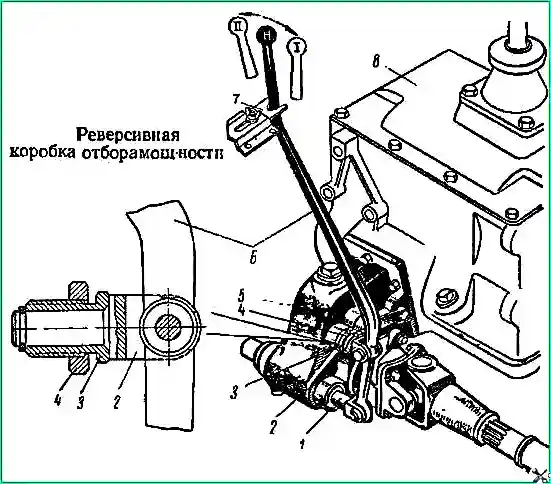
Adjusting the reversible power take-off and its drive
To drive the winch, power take-off box 5 (see Fig. 7◄) has two gears: first gear I for winding the cable (when turned on, lever 6 is moved forward); second gear II for unwinding the cable (when turned on, lever 6 is moved back).
The lever in the neutral position is locked with a latch 7 installed on the cabin floor.
In the reversible power take-off, the preload of the main shaft bearings and the position of the box control lever are adjusted.
The preload of the main shaft bearings is obtained due to the amount of axial clearance of the shaft.
The axial clearance of the main shaft is adjusted using shims.
Reducing or increasing the number of gaskets under the front roof Which bearing, set the required axial clearance.
In this case, it is considered that the bearings are adjusted correctly if the shaft rotates freely by hand (in the absence of an oil seal) and has no noticeable axial play.
When adjusting the preload of the bearings, the bolts securing the covers (front and rear) must be tightened fully by hand to the length of the wrench.
In the neutral position, lever 6 must exactly correspond to the neutral position of the gear, and rod 1 connected to lever 6 must be securely locked.
If the position of the power take-off control lever 6 does not meet the specified requirement, then it is necessary to adjust it with nut 3 with the lock nut 4 loosened, moving the bracket 2 of lever 6 in the axial direction to the desired position.
After completing the adjustment, secure nut 8 of the bracket with lock nut 4.
The adjustment of the lever position should be checked by shifting gears with lever 6 when engaging first gear (winding up) and when engaging second gear (unwinding).