The gearbox is mechanical, three-speed, has five gears for moving forward and one for moving backward
The fifth gear is direct.
The gearbox is equipped with two inertial-type synchronizers for engaging the second and third, fourth and fifth gears.
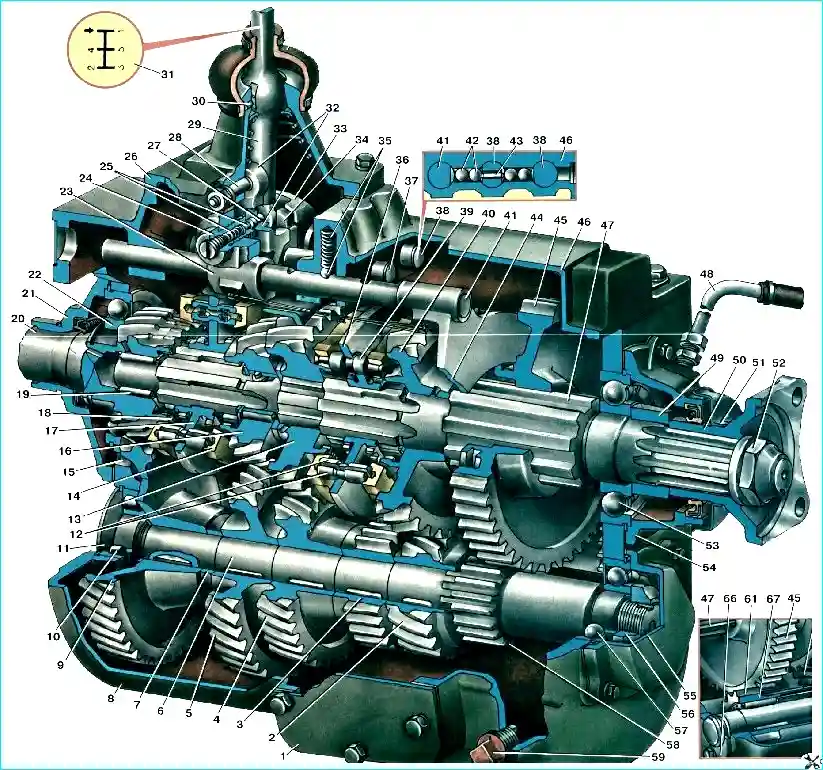
1 - Hatch cover; 2 - Second gear pinion of the intermediate shaft; 3 - Reverse gear; 4 - Third gear pinion of the intermediate shaft; 5 - Fourth gear pinion of the intermediate shaft; 6 - Intermediate shaft; 7 - Spacer sleeve of the intermediate shaft gears; 8 - Gearbox housing; 9 - Constant mesh pinion of the intermediate shaft; 10 - Intermediate shaft roller bearing; 11 - Housing plug; 12 - Synchronizer crackers; 13 - Third gear pinion of the secondary shaft; 14 - Synchronizer cone ring; 15 - Grease outlet window into the gearbox housing; 16 - Fourth gear pinion of the secondary shaft; 17 - Fourth and fifth gear synchronizer carriage; 18 - Inner toothed ring gear; 19 - Front roller bearing of the input shaft; 20 - Input shaft of the gearbox with constant-mesh pinion; 21 - Input shaft bearing cover; 22 - Rear ball bearing of the input shaft; 23 - Head of the first gear and reverse gear engagement slider; 24 - Fuse housing; 25 - Reverse gear engagement safety catch with spring; 26 - Gear shift lever housing; 27 - Reverse gear engagement safety catch rod; 28 - Intermediate lever axis; 29 - Gear shift lever; 30 - Gear shift lever lock; 31 - Ball head and rubber boot of the gear shift lever; 32 - Intermediate lever for moving the first gear and reverse gear engagement slider; 33 - Fork for engaging the second and third gears; 34 - Fork for engaging the fourth and fifth gears; 35 - Slider retainer with spring; 36 - Third and second gear synchronizer carriage; 37 - Slider for engaging the second and third gears; 38 - Slider for engaging the fourth and fifth gears; 39 - Synchronizer locking finger; 40 - Secondary shaft second gear pinion; 41 - Slider for engaging the first gear and reverse; 42 - Slider lock balls; 43 - Slider lock studs; 44 - Fork for engaging the first gear and reverse; 45 - Secondary shaft first gear and reverse gear pinion; 46 - Gearbox housing cover; 47 - Secondary shaft, 48 - Gearbox crankcase ventilation tube; 49 - Thrust sleeve; 50 - Main propeller shaft mounting flange; 51 - Output shaft oil seal cover; 52 - Flange mounting nut; 53 - Secondary shaft rear ball bearing; 54 - Secondary shaft rear bearing cover; 55 - Intermediate shaft rear bearing cover; 56 - Intermediate shaft rear bearing mounting nut; 57 - Intermediate shaft rear ball bearing; 58 - Intermediate shaft first gear pinion; 59 - Magnetic plug for drain hole for oil from crankcase
Gear ratios:
- First gear – 7.44
- Second gear – 4.10
- Third gear – 2.29
- Fourth gear – 1.47
- Fifth gear – 1.00 (direct)
- Reverse – 7.09
The box is attached to the clutch housing on four studs screwed into the body of the clutch housing.
The box is centered on the flange of the rear bearing cover of the input shaft. -
The primary shaft is mounted on two ball bearings.
The front bearing is mounted in the bore of the crankshaft flange, the rear bearing is in the front wall of the gearbox housing.
The rear bearing has a protective washer and is secured from axial movement by a retaining ring installed in the groove of its outer ring.
The front end of the secondary shaft rests on a roller bearing.
The rear end of the secondary shaft rests on a ball bearing secured by a retaining ring in the wall of the housing.
The intermediate shaft is mounted on two bearings.
The front bearing is a roller bearing, without an inner ring; rollers roll directly on the shaft journal.
The retaining ring limits the movement of the outer bearing ring.
The bearing hole in the housing is closed with a plug, which is installed on the paint; when installing the box on the clutch housing, this place is additionally sealed with a rubber ring.
The rear bearing is a ball bearing, with a protective washer and completely filled with balls to increase its service life; the bearing is secured with a retaining ring.
The reverse gear block rotates on two roller bearings mounted on a fixed axle.
The gearbox bearings do not require adjustment.
The primary shaft gear and the intermediate shaft drive gear, the fourth and third, and second gear gears have helical teeth and are in constant mesh with each other, the remaining gears have straight teeth.
The fourth, third and second gear gears of the secondary shaft rotate freely on the corresponding journals of the secondary shaft.
In this case, the contacting surfaces of the second and third gear gears and the shaft, as well as the fourth gear gear and the bushing, work steel on steel.
The bushing is locked from turning on the shaft with a pin.
To prevent jamming and ensure reliable lubrication during operation of the parts, the steel on steel shaft journals and the outer surface of the bushing have a special shape in the form of alternating protrusions and depressions; the surface of these parts is phosphated, and the phosphate layer is impregnated with a special compound that prevents seizure during the running-in period.
When installing gears on the secondary shaft in this way, it is necessary to strictly observe the compliance of the oil used with the lubrication chart requirements.
Using other oils or contaminated oil can cause seizure of the gears on the secondary shaft journals and the bushing.
The gears on the shaft journals are secured in the axial direction with locking rings.
The support washers of the fourth and second gear gears have splined connections with the shaft.
For shock-free engagement of the second and third, fourth and fifth gears, two inertial-type synchronizers are installed in the gearbox; gears have cones for working with synchronizers.
The presence of synchronizers makes it easier to shift gears and increases the service life of the gearbox.
In the right wall of the crankcase there is a threaded plug of the control and filler hole, through which the gearbox is filled with oil in the absence of a power take-off.
If there is a power take-off, oil is poured through the plug in the power take-off.
In both cases, oil is poured to the level of the control and filler hole in the gearbox.
In the left wall of the crankcase at the bottom there is a drain hole closed by a threaded plug, which is equipped with a magnet that attracts small particles of metal from the oil.
In the crankcase on both sides there are two hatches with flanges for mounting power take-off boxes.
A traction winch can be installed on the vehicle upon special request.
In this case, to drive it on the right The power take-off is installed in the gearbox hatch.
Power is taken off from the front rim of the reverse gear block.
The gear shift mechanism is located in the gearbox cover.
The upper part of the cover with the gear shift lever, the intermediate lever for engaging first gear and reverse gear is removable, installed on bushings.
The additional effort required to engage synchronized gears is provided by the ratio of the gear shift lever arms.
The presence of the intermediate lever reduces the travel of the gear shift lever when engaging first gear and reverse gear, as a result of which the lever travel for engaging all gears is the same.
The intermediate lever is locked in the neutral position by the safety pin located in the wall of the gearbox cover.
To engage first gear or reverse gear, it is necessary to use the lever through the intermediate lever pin and the safety pin to compress the safety spring until it stops, then move the lever to the position corresponding to the position of the lever when engaging first gear or reverse.
To remove the upper part of the gearbox cover, you must first unscrew the fuse housing by 8-9 turns.
The gearshift rods are held in the required position by locks consisting of a ball and a spring; there are grooves for the ball on the rods.
To prevent accidental simultaneous engagement of two gears, there is a locking device consisting of a pin and two pairs of balls; when any of the rods is moved, the other two are locked by balls that enter the corresponding grooves on the rods.
Operation of synchronizers
The conical rings of the synchronizer are rigidly connected to each other by means of three fingers, the ends of which are flared.
These fingers have conical surfaces in the middle part, which are locking.
The holes in the carriage disk, through which the locking fingers pass, also have locking surfaces in the form of chamfers on both sides of the hole.
The conical rings are not rigidly connected to the carriage and can be shifted relative to it; they are connected to the carriage via three locking pins, inside which springs and two balls are placed.
Supports for the locking balls are pressed into the rings.
When the carriage is moved, for example, by a fork, the conical ring, moving together with the carriage, is brought to the cone of the gear.
Due to the difference in the numbers of revolutions of the carriageski connected to the secondary shaft and the gear connected through the intermediate shaft to the primary shaft, the conical ring shifts relative to the carriage until the locking surfaces of the fingers touch the locking surfaces of the carriage, preventing further advancement of the carriage.
As soon as the speed of the carriage and gear become equal (synchronization occurs), the locking surfaces will not prevent the carriage from advancing and the gear will engage without noise or impact.
For normal operation of synchronizers and to prevent premature wear of the rings, it is necessary to correctly and promptly adjust the free travel of the clutch pedal.
If the clutch drags, gear shifting becomes difficult.
If synchronized gears are engaged with noise, you should immediately find out the cause of the malfunction and eliminate it to avoid premature failure of the synchronizers.
To prevent oil leakage from the gearbox, the secondary shaft outlet is sealed with a self-tightening rubber seal, additionally protected reflector, and the input shaft has an oil drain groove (auger).
To prevent water from getting into the gearbox when fording, the entry point of the gearshift lever into the gearbox is sealed with a rubber boot with clamping clamps, and the surface of the junction of the gearbox housing with the clutch housing, as well as the gearbox cover, hatch covers and bearing caps are sealed with a special sealing paste.
To prevent pressure build-up in the gearbox or the appearance of a vacuum in it due to temperature fluctuations, the internal cavity of the gearbox communicates with the atmosphere through a ventilation tube installed on the rear wall of the cabin.
Gearbox maintenance
When maintaining the gearbox, it is necessary to check the fastening of the gearbox to the clutch housing, as well as the fastening of the power take-off box (if any), maintain a normal oil level in the gearbox and change it in a timely manner according to the lubrication chart.
Use only the type of oil specified in the chart lubrication.
When changing the oil, it is necessary to clean the magnet of the drain plug and flush the ventilation tube, clogging of which can cause an increase in pressure in the gearbox housing, which leads to oil leakage.
When disassembling the gearbox, it is necessary to check the reliability of the locking and tightening of the nuts; the tightening torque must be at least 25 kgm.
These nuts are locked by pressing the thinned edge of the nut into the groove of the shaft.
The edge of the nut must be pressed into the groove of the shaft with a punch with a rounded end to prevent the edge of the nut from breaking.
The nuts must be unscrewed with a wrench with a long shoulder without first straightening the pressed edge of the nut.
")

")
")
")
")
")
")
")