Engine cooling system is liquid, closed, with forced circulation of coolant
A bypass pipe has been introduced into the cooling system, connecting the lower outlet pipe of the water jacket with the suction cavity of the water pump bearing housing.
The cooling system diagram is shown in Fig. 1.
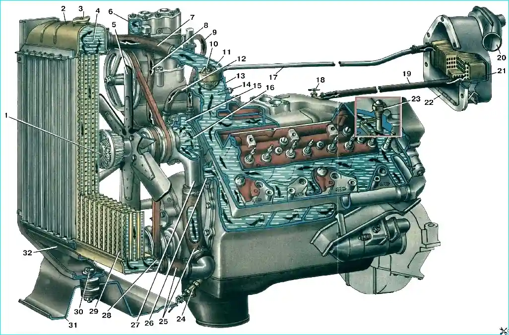
Engine cooling system diagram: 1 - Liquid fan shut-off clutch; 2 - Upper radiator tank; 3 - Radiator plug; 4 - Supply pipe; 5 - Fan blade; 6 - Compressor head cooling jacket; 7 - Supply hose to the radiator; 8 - Hose for draining liquid from the compressor head; 9 - Liquid supply hose to the compressor head; 10 – Thermostat with solid filler; 11 - Upper pipe of the cooling jacket; 12 - Cooling system pump bypass hose; 13 - Lower pipe of the cooling jacket; 14 - Coolant overheating alarm sensor; 15 - Cooling system pump housing; 16 – Impeller; 17 - Heater drain hose; 18 - Cabin heating valve; 19 - Fluid supply hose to the heater; 20 - Windshield blower fan pipe; 21 - Heater radiator; 22 – Heater casing; 23 - Liquid temperature sensor; 24 - Drain tap; 25 - Outlet hoses; 26 - Coolant supply pipe from the cooling system pump; 27 - Bearing housing for the cooling system pump; 28 - Outlet pipe; 29 - Cooling tube plates; 30 - Radiator suspension mounting bolt; 31 – Radiator frame; 32 - Radiator frame reinforcement.
The coolant temperature should be between 80-95° C. Upon special request, an expansion tank can be installed on the vehicle (Fig. 2).
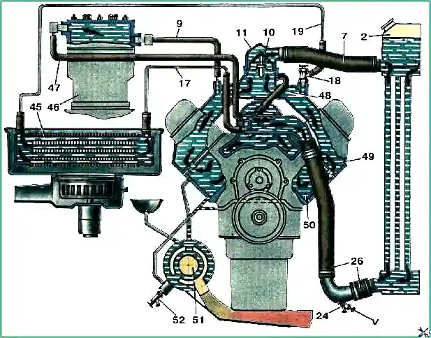
Scheme of operation of the engine cooling system: 2 – upper radiator tank; 7 – supply hose to the radiator; 9 – hose for supplying liquid to the compressor head; 10 – thermostat with solid filler; 11 – upper pipe of the cooling jacket; 17 – hose for draining liquid from the heater; 18 – cockpit heating system; 24 – drain valve; 26 – fluid supply pipe from the cooling system pump; 45 – cabin heater; 46 – compressor; 47 – hose for draining liquid from the compressor head; 48 – cavity for heating the fuel mixture of the intake gas pipeline; 49 – channel for dosing the supply of coolant; 50 – cooling cavity of the cylinder block; 51 – engine preheater; 52 – drain taps of the block jacket and pre-heater boiler
During operation, it is necessary to ensure that the cooling system is always completely filled; The water level should not reach the upper edge of the filler neck by 40-50 mm.
When using a liquid that freezes at low temperatures (antifreeze), its level should not reach the upper edge of the filler neck by 80-90 mm.
If there is an expansion tank, the radiator must be filled completely, and the tank must be filled halfway.
The radiator must be filled with clean and preferably soft water. Do not pour cold fluid into a hot engine.
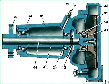
Coolant pump: 33 – pulley mounting flange; 34 – ball bearings; 35 – bearing housing; 36 – plug; 37 – grease nipple; 38 – pump housing; 39 – impeller; 40 – sealing washer; 41 – sealing collar; 42 – reflector; 43 – spacer sleeve; 44 – cooling system pump shaft
In severe frosts, it is necessary to insulate the radiator using insulating covers on the radiator lining and on the engine hood, and carefully monitor the coolant temperature gauge.
Operation of an unheated engine leads to intense wear of the piston rings and cylinders.
To increase the reliability of the cooling system and protect against freezing, during severe frosts, it is recommended to use a special liquid that freezes at low temperatures (antifreeze).
Coolant is poisonous and therefore precautions must be taken when handling it. The entry of even a small amount of this liquid into the body can cause severe poisoning.
When pouring coolant, you must ensure that no air forms in the cooling system ear plug preventing the system from filling.
To avoid this, you need to open the radiator drain valve. The tap should be closed only after liquid appears from it.
The coolant from the cooling system must be drained through three taps: a radiator tap and two starting heater taps.
If there is an expansion tank, a fourth tap is added, installed on its bottom.
You must remember that when draining liquid from the cooling system, you must open all the taps, as well as the radiator cap or expansion tank.
In winter, after draining the water from the system, it is necessary to close the cockpit heater valve and open it again only after starting and warming up the engine.
The cranes are equipped with a remote control (Fig. 3), which ensures easy access to them when the engine hood is open.
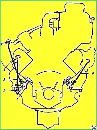
The control handles are located in the engine compartment above the engine.
The heater boiler valve and the expansion tank valve do not have a remote control. Screw valves with ball seal.
If it is necessary to drain liquid from the cooling system, the valve drive handle is unscrewed several turns.
If it is necessary to drain coolant into any container, rubber hoses must be put on the drain taps, the ends of which should be passed into special holes in the under-engine mudguards.
After completely draining the fluid, you should leave the taps open before parking the car.
If the taps freeze in the open position, they must be closed after adding liquid when the engine warms up, after liquid flows from the taps.
When starting a cold engine in winter, you must carefully monitor the thermal operating conditions of the engine.
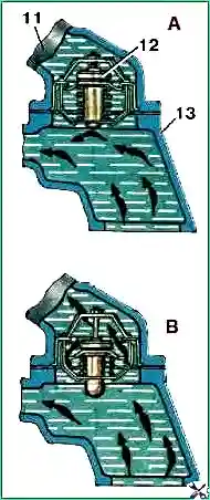
Thermostat operation diagram: 11 – upper pipe of the cooling jacket; 12 – thermostat; 13 – lower pipe of the cooling system; A - the thermostat valve is closed, coolant flows in a small circle; B - thermostat valve is open, liquid flows in a large circle
If the engine is cold, the thermostat valve will prevent coolant from entering the radiator until it warms up in the cylinder block jacket; during this period there is a danger of freezing of the liquid in the radiator
However, during periods of severe frost, it is not permitted to remove the thermostat from the engine cooling system.
You should periodically check the condition of the radiator cap valves.
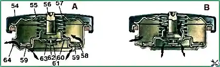
Scheme of operation of the radiator cap: A – steam valve is open; B – air valve open; 54 – plug cover; 55 – thrust spring of the cover washer; 56 – exhaust valve stem; 57 – exhaust valve spring; 58 – exhaust valve plate; 59 – valve sealing washers; 60 – intake valve cup; 61 – intake valve spring; 62 – intake valve stem; 63 – valve sealing washers; 64 – steam outlet
It is necessary to systematically monitor the condition of all seals and prevent fluid leakage from the cooling system.
It is strictly prohibited to start and short-term operation of the engine without coolant in the cooling system, as well as warming up the engine after draining the coolant to remove the remaining coolant from the system, as this can lead to destruction of the rubber sealing rings of the cylinder liners, loss of valve seats, burnout of the head gasket and warping of the aluminum head.
In cases where the cooling system is dirty, it must be flushed.
In the summer, it is necessary to systematically monitor the condition of the air channels of the radiator core of the cooling system and be sure to clean them if they are significantly clogged.
Cleaning can be done with a jet of compressed air directed into the air channels of the radiator core from the side of the fan casing.
")

")
")
")
")
")
")
")