The transfer case is mechanical, has two gears
Gear ratio of first gear 2.08, second gear 1.0
The transfer case is rigidly attached with four bolts to the longitudinal frame beams, which, in turn, are attached to the frame cross member brackets on rubber pads.
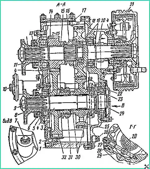
Fig. 1. Transfer case of a ZIL-131 car: 1 - crankcase; 2 - tray; 3 - front axle drive shaft; 4 - retaining ring; 5, 24 - covers; 6 - oil deflector ring; 7 - filler plug; 8, 11 - flanges; 9 - flange nut; 10 - air-diaphragm chamber for engaging the front axle drive; 12 - drive shaft; 13 - oil seal; 14 - drive gear; 15 - key; 16 - second gear shift carriage; 17 - hatch cover; 18 - side crankcase cover; 19 - driven shaft with gear; 20 - speedometer worm; 21 - hand brake drum; 22 - front axle drive fork; 23 - carriage for engaging the front axle drive; 25 - second gear gear; 26 - drain plug; 27 - speedometer fitting; 28 - locking plate; 29 - speedometer driven gear; 30 - needle bearings; 31 - first gear shift carriage; 32 - first gear gear; 33 - first gear fork; 34 - locking bolt; 35 - second gear fork; 36 - second gear engagement rod; 37 - retainer spring plug; 38 - spring; 39 - locking ball; 40 - rubber ring; 41- felt ring; 42 - oil seal nut; 43 - switch for the warning lamp indicating that the front axle is turned on; 44 - breather; 45 - housing of clamps; 46 - balls of the locking mechanism; 47 - first gear engagement rod; 48 - switch of the electromagnet of the electropneumatic valve; 49 - air-diaphragm chamber housing; 60 and 65 - diaphragms; 51 - return spring; 52 – rod
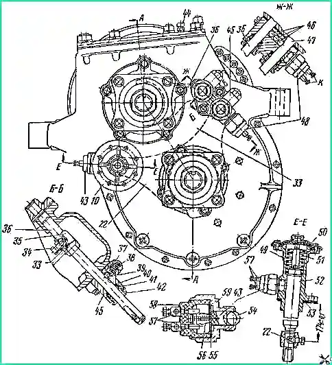
Fig. 2. Transfer case of a ZIL-131 car: 1 - crankcase; 2 - tray; 3 - front axle drive shaft; 4 - retaining ring; 5, 24 - covers; 6 - oil deflector ring; 7 - filler plug; 8, 11 - flanges; 9 - flange nut; 10 - air-diaphragm chamber for engaging the front axle drive; 12 - drive shaft; 13 - oil seal; 14 - drive gear; 15 - key; 16 - second gear shift carriage; 17 - hatch cover; 18 - side crankcase cover; 19 - driven shaft with gear; 20 - speedometer worm; 21 - hand brake drum; 22 - front axle drive fork; 23 - carriage for engaging the front axle drive; 25 - second gear gear; 26 - drain plug; 27 - speedometer fitting; 28 - locking plate; 29 - speedometer driven gear; 30 - needle bearings; 31 - first gear shift carriage; 32 - first gear gear; 33 - first gear fork; 34 - locking bolt; 35 - second gear fork; 36 - second gear engagement rod; 37 - retainer spring plug; 38 - spring; 39 - locking ball; 40 - rubber ring; 41- felt ring; 42 - oil seal nut; 43 - switch for the warning lamp indicating that the front axle is turned on; 44 - breather; 45 - housing of clamps; 46 - balls of the locking mechanism; 47 - first gear engagement rod; 48 - switch of the electromagnet of the electropneumatic valve; 49 - air-diaphragm chamber housing; 60 and 65 - diaphragms; 51 - return spring; 52 – rod
Shift the transfer case gears using lever 1 (Fig. 3), which has three positions.
When the lever is in the rear position, the second (direct) gear is engaged, when the lever is in the forward position, the first (lower) gear is engaged, the middle position is neutral.
To prevent the simultaneous engagement of two gears, a ball-type locking mechanism is used (see Fig. 1).
To make driving easier in difficult off-road driving conditions, as well as to prevent transmission overloads, the car has an electro-pneumatic front axle engagement control, which ensures automatic engagement of the front axle when first gear is engaged in the transfer case.
The ZIL-131 vehicle is equipped with a two-way transfer case, which has two output shafts rotating on ball and roller bearings.
The advantage of these bearings is that they do not require adjustment, both during assembly and during operation, as required by tapered roller bearings
The transfer case has a device against self-switching of gears
The anti-self-shutdown device is made on the splines of both gears 25 and 32, located on the and shaft 3 – front axle drive.
This device protects the first gear engagement carriage 31 and the front axle drive engagement carriage 23 from self-switching
The second gear self-switching design has a different device
On the outer rim of the carriage 16 for engaging the second gear and the associated spline hole of the driven shaft 19 there is a cone device, i.e. the thickness of the tooth and the width of the groove along the length of the same diameter are variable, i.e. there is a reverse cone, which and prevents self-shutdown
To prevent the simultaneous engagement of two gears, the transfer case has a locking device consisting of 46 balls between rods 36 and 47.
When one of the rods moves, the balls move towards the other and lock it
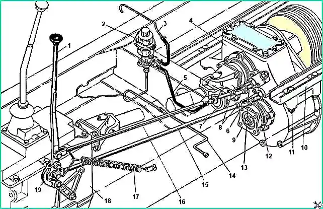
Transfer case control drive of the ZIL-131 car: 1 - gear shift lever; 2 - electro-pneumatic valve; 3 - breather tube; 4 - transfer case; 5 - air supply hose to the air-diaphragm chamber; 6 - traction fork; 7 - air-diaphragm chamber; 8 - lock nut; 9 - front axle drive shaft flange; 10 - longitudinal beam; 11 - transfer case mounting bolt; 12 - first gear engagement rod; 13 - second gear engagement rod; 14 - air supply tube to the electro-pneumatic valve; 15 - first gear engagement rod; 16 - second gear engagement rod; 17 - tension spring; 18 - gearbox; 19 - lever earring
Gear ratio of the speedometer drive pair is 3.4.
Pour oil into the transfer case through the control-fill hole, closed with a plug to the level of this hole.
Drain the oil through the drain hole, in the plug of which there is a magnet that attracts metal particles that get into the oil.
To prevent oil leakage from the transfer case, the exit points of all shafts are sealed with self-clamping rubber seals
The front axle drive shaft oil seal, located below the oil bath level, is additionally protected by an oil stripper washer
All joints of the transfer case housing, bearing caps and top hatch are sealed with a special paste.
For all work related to disassembling the transfer case, all crankcase parts should be put in place using the mentioned paste.
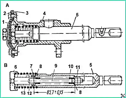
Air-diaphragm chamber for engaging the front axle drive: A – chamber assembly; B – chamber rod assembly; 1 – diaphragm; 2 – bolt; 3 – cover; 4 – camera body; 5 – outer rod of the chamber; 6 – glass; 7 – retaining ring; 8 – washer; 9 – internal rod; 10 – pressure spring; 11 – nut; 12 – rod flat; 13 – return spring
The figure shows separately the air-diaphragm chamber for engaging the front axle drive and the rod assembly of this chamber
The transfer case has a hatch for installing a power take-off
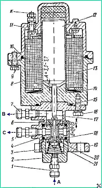
Electro-pneumatic valve: 1, 5, 7 – fittings; 2 – plug; 3 – valve spring; 4 – valve seat; 6 – exhaust valve; 8 – electromagnet housing; 9, 16 – bolts; 10, 15, 18 – sealing rings; 11 – cover; 12 – core; 13 – electromagnet winding; 14 – spacer washer; 17 – rod; 19 – body; 20 – inlet valve; 21 – nut; B - to the breather; C - to the air-diaphragm chamber; A - from the brake valve
The design of the electro-pneumatic front axle drive control valve is shown in Figure 5
In the de-energized state, the electro-pneumatic valve is closed by spring force 3, and the air-diaphragm chamber 10 (Fig. 1) communicates with the atmosphere through the breather
When voltage is applied to the windings 13 of the electromagnet, the core 12 pushes the rod 17, overcoming the force of the spring 3 and the resistance of the compressed air, and opens the inlet valve 20
In this case, compressed air enters the above-membrane cavity of the air-diaphragm chamber for controlling the front axle drive
The transfer case suspension is made on two longitudinal beams resting on the frame cross members
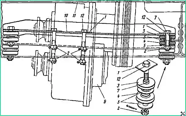
Transfer case suspension: 1, 5, 8 – washers; 2 – nuts; 3, 4 – pillows; 6 – hairpin; 7 – spacer sleeve; 9 – transfer case; 10 – beam for fastening section grinding box; 11 – frame; 12 - bolts
The beams on the frame cross members have an elastic suspension, as they are reinforced with bolts having rubber pads installed on both sides of the support
The transfer case is suspended from two longitudinal beams by four bolts passed through the holes in the longitudinal beams, as well as the nuts of the transfer case mounting bolts are cottered
Technical characteristics of the transfer case
Type – mechanical, two-way, two gears
Gear ratios:
- - first gear – 2.08;
- - second gear – 1.00
Gear shift - one rocker lever and two rods
Front axle engagement is automatic and forced. Automatic activation is carried out using an electrical sensor that is activated when first gear is engaged. Forced - using an electric switch in any gear. When automatically and forcedly switched on, the electro-pneumatic valve and air-diaphragm chamber are activated
The drive of the middle and rear axles is carried out from the driven shaft of the transfer case through one driveshaft
Caring for the transfer case
During operation, it is necessary to check the reliability of fastening of the transfer case to the longitudinal beams of the frame and the reliability of fastening of the beams themselves to the cross members of the frame; It is necessary to periodically tighten the fastening bolts.
It is also necessary to periodically flush and clean the air channels of the breather installed on the transfer case hatch cover, clogging of which can cause an increase in pressure in the transfer case crankcase; this may cause oil leakage through the oil seal.
It is necessary to maintain a normal oil level in the box and change it in a timely manner according to the lubrication chart.
When disassembling the transfer case, remember that the shaft end nuts are locked in the same way as on the gearbox.
When installing the air chamber of the front axle shift carriage, it is necessary, using shims 42, to adjust the size 174 ± 0.1, from the end of the chamber housing 38 to the hole for the locking bolt on the shift rod in accordance with Fig. 2.
")

")
")
")
")
")
")
")