The car is equipped with a winch designed to pull the car out when overcoming difficult sections of the road, as well as to provide assistance to other cars stuck on the way
The winch (Fig. 1) is installed at the front of the vehicle, bolted to the front buffer and front frame cross member.
The front buffer is bolted to removable side member extensions.
The winch is driven by a cardan shaft from the power take-off mounted on the gearbox.
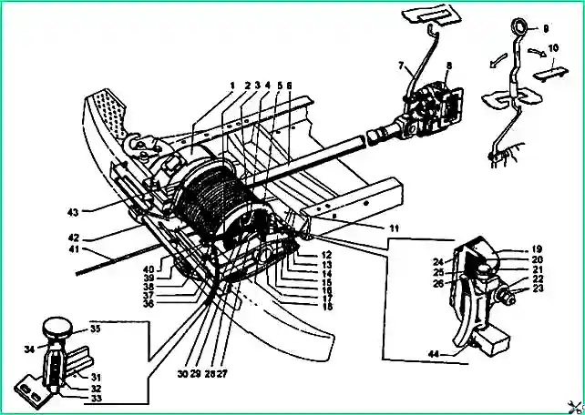
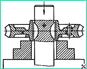
Winch of a ZIL-131 car: 1 - winch gearbox; 2 and 31 - drum activation fork; 3 - nut of the cable fastening bracket, 4 - cable fastening bracket; 5 - drum; 6 - driveshaft, 7 - power take-off control lever; 8 - power take-off; 9 - spanner wrench, 10 - cabin floor hatch cover; 11 - bracket for attaching the winch to the cross member; 12,15, 25, 37, 38 - bolts; 13 - rear cross member for winch installation; 14, 23 and 36 - nuts; 16 - drum shaft traverse; 17 - adapter; 18 and 30 - oilers; 19 - brake pad; 20 - screw; 21 - drum mounting fork pin, 22 - pressure bolt guide; 24 - friction lining of the brake pad; 26 - brake pad pressure spring; 27 - drum thrust ring, 28 - front cross member for winch installation; 29 - sliding drum engagement clutch, 32 - locking spring, 33 - drum engagement fork retainer; 34 - pin, 35 - drum fork handle; 40 - latch lock plate, 41 - winch cable with hook; 42 - guide roller; 43 - safety bracket; 44 - cotter pin
Winch drum 5 rotates freely on the shaft and is rigidly connected to the shaft using coupling 29.
When the handle of the drum engagement fork 35 is moved to the extreme left position, the drum engagement coupling moves on the shaft along two keys and the end cams engage with the end cams of the drum.
The drum switching fork is installed on the winch traverse.
The shift fork is equipped with a brake block, hinged in the traverse ears on the axle.
When the clutch is disengaged, the brake shoe, under the action of a pressure bolt with a spring, rests against the end of the drum flange, slows down its rotation and prevents the possibility of the cable unraveling when unwinding it manually.
The brake is adjusted by tensioning or loosening the spring of the thrust bolt using a nut with a lock nut, and if necessary (when the spring force is insufficient) by moving this bolt by screwing in or unscrewing the threaded bushing.
The spring pressure is adjusted correctly if the cable unwinds under the influence of hand force without self-unraveling. There is a depression on the inner side of the drum flange into which the end of the cable is placed, securing it with a bracket and nuts.
The winch cable is steel, non-unwinding, with a metal core. A hook is attached to the free end of the cable.
The drum shaft rotates in three bronze bearings, two of which are installed in the gearbox housing and one in the yoke.
The cross member and the gearbox housing are bolted to the cross members.
The drum shaft bearing in the traverse is lubricated through oiler 30.
The drum shaft bearings in the gearbox housing are lubricated by oil flowing from the gearbox worm wheel and from the walls of the crankcase cover.
The rotation surfaces of the drum on the shaft are lubricated through two oil nipples 18 located at the drum hubs.
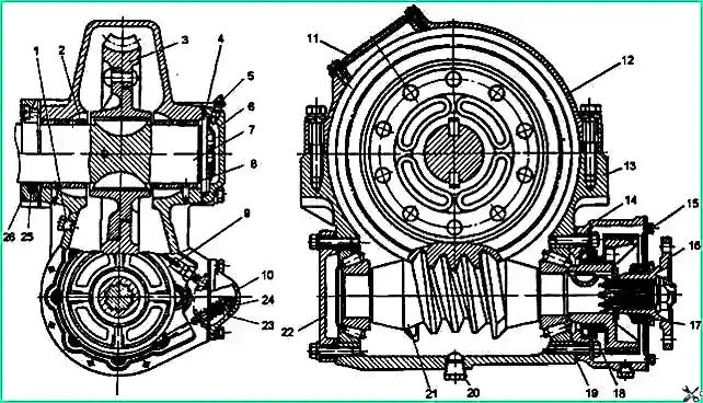
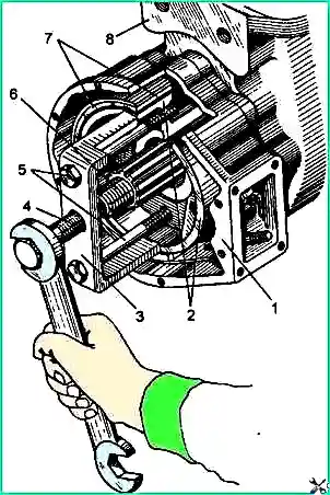
Winch gearbox: 1 - control plug; 2 - drum shaft bearing; 3 - worm wheel, 4 - mounting washer; 5 - oiler; 6 and 26 - thrust covers; 7 - drum shaft; 8 and 19 - shims, 9 - brake band; 10 - brake spring cover, 11 - inspection hatch cover; 12 - crankcase cover; 13 - gear housing; 14 and 22 - bearing caps; 15 - brake drum, 16 - flange; 17,18 and 25 - cuffs; 20 - gearbox housing drain plug; 21 - worm; 23 - spring; 24 - adjusting nut
The winch gearbox (Fig. 2) consists of a globoid single-throw steel worm 21, a worm wheel 3 with a bronze rim, a split housing, a drum shaft 7, an automatic brake, bearings and their covers.
The worm wheel of the gearbox is mounted on the winch drum shaft on two keys and secured against axial movements with a pin.
The movement of the drum shaft with the worm wheel in the axial direction is carried out by changing the thickness of the set of gaskets under the washer 4, installed between the right end of the gearbox housing and the end of the recess in the cover 6. Washer 4 at secured to the end of the shaft with bolts.
There is an inspection hatch in the gearbox housing cover, closed with a cover 11.
Worm 21 is installed in the gearbox housing 13 on two tapered roller bearings.
The bearings are closed with covers 14 and 22. A cuff 18 is pressed into the cover 14. The bearing covers are attached to the gearbox housing with bolts.
At the rear end of the worm shaft there is a drum 15 for the automatic brake of the winch gearbox and a flange 16 for fastening the propeller shaft.
The brake drum is mounted on a key, and the flange is mounted on splines; They are secured with a nut against axial movements. The brake drum is covered with a cover. The cover has a felt cuff 17 that prevents dirt from getting into the brake.
Between the end of the inner ring of the bearing and the end of the brake drum hub there is a sealing ring made of copper or paronite.
The drum is braked by brake band 9 with a friction lining. One end of the brake band is rigidly fixed in the wall of the bearing cover, and the other is movably fixed through a spring.
The spring tightens the tape in the direction opposite to the rotation of the worm shaft when winding the winch cable. The tape, under the influence of friction, compresses the spring, which leads to a weakening of the pressure of the tape on the drum, that is, to a decrease in braking
Due to the rigid fastening of the opposite end of the tape during reverse rotation under the influence of friction, the tape self-tightens, causing the worm to slow down.
At a low rotation speed of the worm shaft, the braking force created by the automatic brake is insignificant and does not prevent the cable from unwinding.
In the event of a shear as a result of an overload of the safety pin, when the winch drum begins to rotate in the opposite direction at an increased speed, the braking effect becomes significant and serves as an addition to the self-braking action of the worm gear, which prevents the rapid rotation of the winch drum and the unwinding of the cable.</p >
The tension of the brake band is adjusted with nut 24.
When the nut is rotated clockwise, the spring pressure increases. The brake must be adjusted so that when the cable unwinds, its drum does not heat up excessively
The winch cable guides are bolted to the lower flange of the front buffer and the rear cross member of the winch.
In front, between the guides, there is a guide roller for the winch cable and a rod that keeps the cable from falling out.
The roller rotates on an axis secured with nuts in the guides. Lubricate the roller bearings through an oiler installed at the left end of the roller axis.
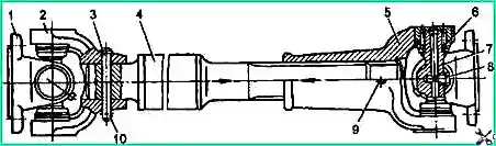
Winch drive drive shaft: 1 - flange; 2 - propeller shaft fork: 3 - safety pin: 4 - shaft with a splined end; 5 - sliding fork of the winch cardan; 6 - cardan cross bearing; 7 - cardan cross; 8 - plug; 9 - grease fitting; 10 - cotter pin
The driveshaft of the winch (Fig. 3) is tubular, with two hinges. A fork with a safety pin is installed at the front end of the propeller shaft, and a sliding fork is installed at the rear end with splines.
When the load increases above the limit, the pin is cut off, protecting the winch parts from breakage.
Maintenance of the winch consists of checking and tightening all fastening parts, lubricating the bearings, changing the oil in the gearbox, checking the quality of the seals, adjusting the bearings, checking and adjusting the axial clearance of the drum shaft and the engagement of the worm gear</ p>
The winch gear housing is filled with oil through the hatch in the upper part of the gearbox to the level of the inspection and filling hole.
After 15-20 pull-ups of the car, you need to check the oil level.
If necessary, add oil up to the level of the inspection hole. The oil in the gearbox should be changed within the periods specified in the lubrication chart.
The hinges, splined joints of the drive shafts of the winch drive, the bearings of the drum shaft and the guide roller must be lubricated according to the lubrication chart.
Removing the winch from the car
Disconnect the cardan drive. Loosen the brackets 9 (Fig. 4) from the fastening and remove them together with the guide roller 14 and the cable guide rod 13.
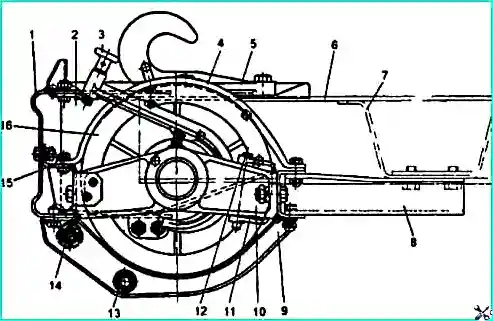
Installing the winch (left view): 1 - front buffer, 2 - removable brackets for the front frame buffer; 3 - winch drum activation fork, 4 - winch safety bracket; 5 - towing hook; 6 - frame; 7 - first cross member; 8 - front buffer mounting bracket; 9 - bracket with guide roller and rod assembly; 10 - traverse; 11 - block then winch drum brake; 12 - drum fork finger; 13 - rod guiding the winch cable; 14 - roller guiding the winch cable; 15 - front cross member for winch installation; 16 - winch drum
Unscrew the bolts securing the safety bracket 4 of the winch to the front cross member 15 of the winch and remove the bracket.
Release the removable brackets 2 of the front buffer from their fastening. Unscrew the bolts securing the front buffer brackets to the frame and the bolts securing the front winch cross member to the front buffer.
Unscrew the bolts securing the front buffer to the mounting brackets of the front buffer 8. Using a lift, remove the front buffer assembly with the winch and disconnect it from the buffer. Place the winch on the stand for disassembly.
Before disassembling, clean the winch from dirt and dust, wash it in a degreasing solution and blow it with compressed air. Disassembly of the winch is carried out in exceptional cases, since it does not work continuously and its parts do not wear out intensively.
Disassembling the winch
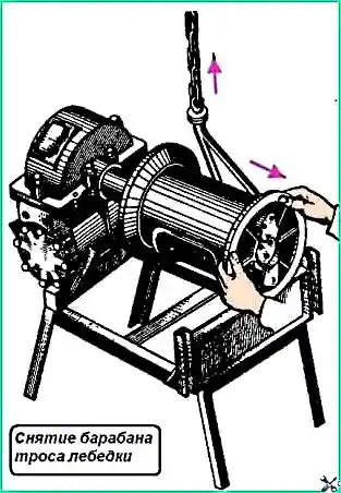
Removing the drum.
Unwind the cable, unscrew the bolts securing the traverse 10 to the winch cross members, remove the cotter pin and knock out pin 12 of the winch drum engagement fork, then remove the traverse, brake pad 11, winch engagement clutch, remove the keys from the grooves of the shaft, remove winch cable drum 16 (Fig. 5).
During disassembly, it is prohibited to remove drum 15 (see Fig. 2) of the winch worm brake by screwing the bolts all the way into the cuff, which leads to its damage and loss of tightness.
To ensure that the bolts do not rest against the cuff, you should screw the bolts in 7-8 mm, hook the bolts with a puller and remove the drum.
Disassembling the winch gearbox
Unscrew the bolts and remove covers 6 and 26 (see Fig. 2).
Unscrew and unscrew the installation bolts of drum shaft 7 and remove the installation washer 4 and adjusting shims 8.
Unscrew the fastening bolts and remove the cover 12 of the gearbox housing 13.
Remove drum shaft 7 assembled with worm wheel 3.
Unlock the nut securing the flange 16 of the worm shaft 21 of the gearbox, unscrew the nut, remove the washer and flange manually.
If the flange cannot be removed manually, use a mod. 20P-7968.
Unscrew the bolts securing the automatic brake cover of the winch gearbox, remove the cover with cuff 17 assembled and the thrust washer.
Unscrew the bolts of the cover 10 of the spring 23 and remove the cover. Unscrew the brake band nuts and remove the band 9.
Remove brake drum 15 with cuff using a puller.
The method of removing the winch brake drum is shown in Fig. 5.
Unscrew the fastening bolts and remove covers 14 and 22 with gaskets (see Fig. 2).
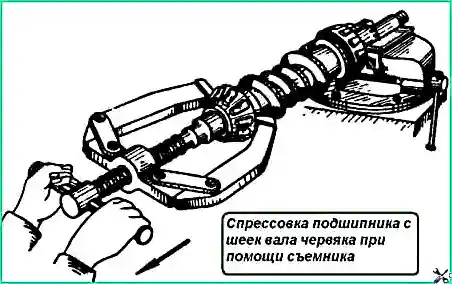
Install the gearbox housing 13 complete with the worm on the press and press out the worm shaft assembled with the bearing rings (Fig. 7).
In this case, one outer ring of the bearing is pressed out. If necessary, another ring can be pressed out using a mandrel or puller.
Removing the winch brake drum: 1 - rear gearbox bearing cover; 2 - brake drum; 3 - bracket of a removable device; 4 - thrust screw of the device; 5 - coupling bolts of the device; 6 - gear worm; 7- gear brake band; 8 - gear housing
Press the inner rings of the bearings from the worm shaft using a puller mod. 20P-7968 (Fig. 6).
Remove bearings 2 (see Fig. 2) of the winch drum shaft, press out the pin connecting shaft 7 and worm wheel 3.
Install the worm wheel under the press on a hollow stand, guiding the drum shaft through it, then press the shaft out of the worm wheel hub (Fig. 9) and remove the keys from the shaft grooves.
Disassembling the winch driveline
Disassembling the driveline drive of a winch is carried out similarly to disassembling the driveline drive of a car.
The driveline drive system of the winch is shown in Fig. 3
Parts winches
If there are cracks and breaks on the gearbox housing, covers and other parts of the winch, they should be replaced.
Welding of several cracks on parts made of gray and ductile cast iron is allowed. Damage to the threads on the winch parts is allowed no more than two threads.
Worn holes in the gearbox housing for the outer rings of the bearings should be repaired by installing repair bushings.
Misalignment between the bored hole in the crankcase and the hole in the repair sleeve for the bearing is allowed no more than 0.05 mm.
Non-perpendicularity of the crankcase ends the duct under the bearing caps relative to the surface of the holes for the bearings is allowed no more than 0.08 mm.
Worn journals of shafts and axles of over-permissible dimensions can be repaired by chrome plating followed by processing to the nominal dimensions.
Shafts that are bent or twisted must be replaced.
The runout of the journals of the worm shaft under the bearing is allowed no more than 0.05 mm. The runout of the end surfaces of the worm shaft at the interface with the bearings is no more than 0.03 mm.
The runout of the end of the worm wheel (when installing the shaft on supports) is no more than 0.12 mm. The runout of the end of the shaft mounted on supports by journals is no more than 0.06 mm.
Bearings with increased play, cracked rings, nicks and corrosion spots on the working surfaces should be replaced.
There should be no damage to the mating surfaces on the flanges. Any nicks on the flange surface or on the brake drum should be removed by sanding.
If there is wear on the fork legs in the drum activation mechanism or wear on the groove in the sliding clutch of over-permissible dimensions, they should be replaced.
A bent fork can be repaired by straightening. If a worm tooth or worm gear tooth of a worm wheel exceeds the permissible dimensions breaks or wears out, they should be replaced.
Brake bushings and friction linings worn out beyond the permissible size must be replaced.
Misalignment of the internal surfaces of the pipe bushings of the cable guide roller is allowed no more than 0.1 mm.
Assembling and adjusting the winch
Before assembly, winch parts must be washed in a degreasing solution, blown with compressed air and checked for suitability for assembly. In case of damage, cuffs, seals and gaskets must be replaced with new ones.
The winch is assembled in the reverse order of disassembly.
Before pressing in the cuff of the gear worm bearing cover, the outer surface of the cuff casing and the cuff seat should be lubricated with a thin layer of AK-20 glue.
When installing the gearbox bearing caps, the tapered roller bearings must be preloaded.
The torque required to rotate the worm shaft in the bearings should be 0.1-0.6 Nm.
After adjustment, the worm shaft should rotate freely with the bearing cap bolts fully tightened, but have no axial play.
Adjustment of tapered bearings is carried out using adjusting shims placed under the flange of the covers.
If the worm shaft rotates too freely or has axial play, it is necessary to remove part of the spacers of equal thickness from under the front and rear bearing caps; if the worm shaft rotates with a torque of more than 0.6 Nm, shims of equal thickness should be added under both bearing caps.
The number of gaskets under the rear and front bearing caps should be approximately the same or have a difference in gasket thickness of no more than 0.1 mm.
The thickness of the gaskets under the covers can only be changed by adjusting the engagement of the worm gear teeth.
Adjustment of the tapered bearings of the gearbox is carried out before installing the worm wheel assembly with shaft, flange and brake drum into the gearbox.
After adjusting the brake, the bolts, gaskets and nuts securing the brake drum should be installed with AK-20 glue.
After installing the worm wheel on the winch shaft, the pin should be pressed in and cored.
Before installing the drum shaft with worm wheel assembly, you should check the wear of the bushings and journals of the drum shaft.
The permissible gap between the diameter of the bushings and the journals should not exceed 0.6 mm.
If the gap is larger, the bushings must be replaced. The bushing locating pin must not protrude beyond the surface of the inner diameter of the bushing.
After installing the activation mechanism and traverse on the drum shaft, secure the installation washer and adjust the axial movement of the shaft.
The shaft should rotate freely, but should not have an axial play of more than 0.1 mm (as measured by an indicator on the left end of the drum shaft) when the wheel moves in the axial direction.
After adjusting the worm shaft bearings and adjusting the axles For the drum shaft clearance, it is recommended to check the correct engagement of the teeth of the worm wheel and the worm on the “paint” along the contact patch.
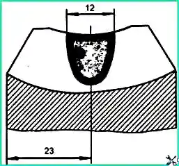
When the gear is correctly adjusted, the contact patch on the working side of the worm wheel tooth should correspond to the patch shown in Fig. 10.
The correct location of the contact patch relative to the axis of symmetry of the tooth is achieved by corresponding movement of the drum shaft with the worm wheel in the opposite direction to the displacement of the contact patch.
To move the worm wheel with the drum shaft to the right or left, you should remove or add some spacers under the end of the support washer
Adjusting the size of the contact patch along the tooth height is achieved by moving the worm relative to the worm wheel; to do this, you need to move the spacers from under the bearing cap from one side to the other, without changing the preload in the bearings.
A worm gear can only operate reliably if it is properly engaged.
Incorrect adjustment causes the gearbox to become overheated.
When installing an automatic brake, it must be adjusted.
The result of the adjustment must be checked during the process of unwinding the cable, while the brake drum should not become very hot from the friction of the brake band.
Weak smoke from the brake band during running-in cannot serve as a rejection sign.
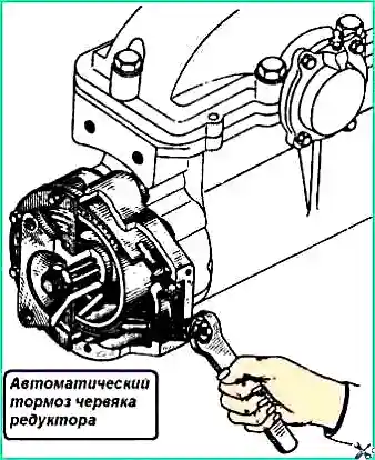
The tension of the brake band is adjusted with a nut (Fig. 11), when rotated to the right, the tension of the band and braking increases.
To check the tightness of the worm brake, it is permissible to remove the gearbox brake cover and the spring cover before winding the cable onto the drum.
The gap between the coils of the brake band spring should be within 1-1.5 mm.
After assembling the winch, you need to check the operation of the winch drum activation mechanism.
When the clutch is turned off, brake shoe 2 (Fig. 12) should slow down drum 1 when rotating the drum, which will prevent the possibility of the cable unraveling when unwinding manually.
The brake is adjusted by tensioning or loosening the spring of pressure bolt 3 using a nut with a lock nut, and if necessary (when the spring force is not enough) - by moving this bolt by screwing in or unscrewing the guide pressure bolt.
The brake spring pressure is adjusted correctly if the cable unwinds under hand pressure without unraveling.
When installing the winch cable guide roller, tighten the roller mounting nut, applying a torque of 120 Nm, and bend the edges into the groove.
Installing a winch on a car
Attach the front and rear cross members to the winch. Connect the front buffer to the front cross member of the winch.
Install the winch assembly with the front buffer on the car frame using a lifting device and secure the rear winch cross member to the first frame cross member, and the buffer assembly with removable brackets to the frame side members.
Attach the safety bracket to the front winch cross member and the first frame cross member at the same time as the rear winch cross member.
Attach the cable guide roller bracket from below to the front buffer and rear cross member of the winch.
Attach the cardan drive to the gearbox flanges and the power take-off mounted on the gearbox hatch.
Check the correct position of the power take-off lever; make adjustments if necessary.
Start the engine, including the power take-off gears, check the operation of the winch.
")

")
")
")
")
")
")
")