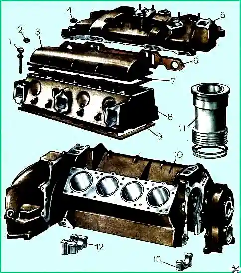
The engine cylinder block is cast iron, with insert liners made of gray cast iron with an acid-resistant insert in the upper part of the liner by clamping the liner collar between the block and the cylinder head through an asbestos steel gasket, and in the lower part by two rubber rings
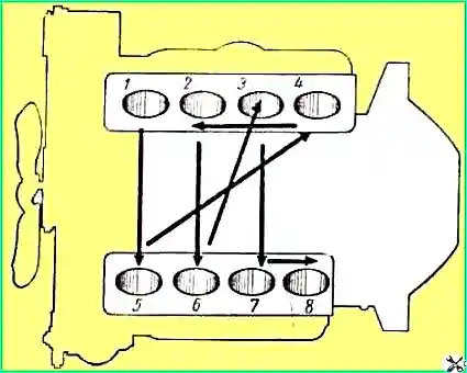
Cylinder numbering is indicated on the engine intake pipe pipes.
The order of the cylinders and the sequence of their operation are shown in Figure 1.
The cylinder headis made of aluminum alloy with insertable seats and valve guides
Asbestos steel gaskets are installed between the block and the heads.
Each cylinder head is attached to the cylinder block with seventeen bolts, which include four bolts securing the rocker arm axle.
The bolts securing the heads to the block must be tightened with a special torque wrench, which allows you to control the tension torque, since the aluminum block head, when heated, increases in height more than the steel bolts securing it.
When the engine warms up, the tightening of the cylinder head increases, and when it cools, it decreases, so the tightening torque of the cylinder head bolts should be 7-9 kgm on a cold engine
Moreover, at an engine temperature below minus 5°C, the tightening torque of the bolts should be closer to the lower limit (7 kgm), and at a temperature of plus 20-25°C - closer to the upper limit (9 kgm).
When the engine is fully heated, the tension of the cylinder heads automatically increases to the required limit.
Simultaneously with tightening the bolts securing the cylinder heads, it is necessary to tighten the bolts securing the exhaust gas pipelines, as well as the clamps for sealing the components of the gas pipelines.
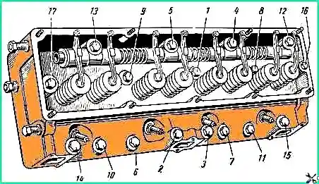
To ensure complete contact between the planes of the heads and the block, it is necessary to follow the order of tightening the bolts shown in Fig. 2.
Tighten the cylinder head bolts evenly, in two steps.
After tightening all the bolts, you need to additionally tighten bolts 1, 2, 3, 4 and 5.
When changing gaskets, you must clean all water holes in the cylinder heads and cylinder block.
The head cover fastening nuts must be tightened evenly with a tightening torque of 0.5-0.6 kgm
")

")
")
")
")
")
")
")