Design of contact ignition system ZIL 131
The engine is equipped with a shielded, sealed battery ignition system, consisting of a B 102-B ignition coil, a P102 ignition distributor, CH307 spark plugs and high voltage wires in shielding hoses and manifolds, as well as an ignition switch
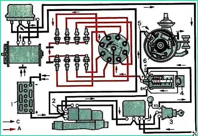
An additional resistance SE102 is connected in series with the coil, which is automatically short-circuited at start-up to compensate for the drop in battery voltage associated with turning on the starter.
The additional resistance is not sealed, and therefore it is mounted above the ford level.
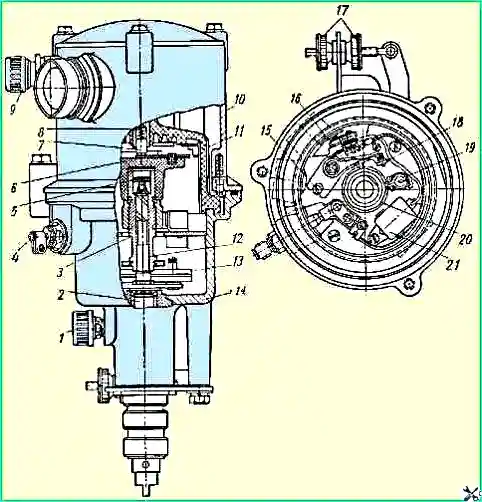
Ignition distributor: 1 - oiler: 2 - distributor shaft: 3 - cam bushing; 4 - shielded low voltage terminal; 5 – felt; 6 - slider; 7 - contact angle; 8 - contact carbon spring; 9 - output of the high-voltage wire to the ignition coil; 10 - distributor screen with bushings for screening hoses of high-voltage wires; 11 - distributor cap; 12 - centrifugal regulator roller; 13 - centrifugal regulator; 14 - distributor body: 15 - adjusting screw (eccentric); 16 - breaker lever with moving contact; 17- octane corrector adjusting nuts; 18 - stand with fixed contact: 19 - cam lubrication filter; 20 - distributor cam; 21 - capacitor
Distributor P102 is sealed, shielded, eight-spark, with a centrifugal ignition timing regulator.
To smoothly adjust the ignition timing depending on the type of fuel used, an octane corrector is used, consisting of two plates, one of which is attached with a bolt to the distributor body, and the second with two bolts to the drive housing (on the cylinder block).
By rotating the octane corrector adjusting nuts, mutual movement of the plates is achieved and, accordingly, rotation of the distributor body is achieved.
To provide access to the high voltage sockets on the distributor cover, the shielding cap cover is made removable and secured with three bolts.
To access the breaker, the entire shielding cap is removed, which in turn is also secured with three bolts to the distributor body.
When disassembling the screen, pay special attention to the safety of the sealing gaskets.
The inputs of the low and high voltage wires from the ignition coil are sealed with rubber rings to seal the landing shank of the distributor housing; a groove is made on it in which a rubber sealing ring is placed.
The distributor is sealed, as it is designed to work underwater (fording).
In order to avoid accelerated burning of the breaker contacts, damage to high-voltage plastic parts and corrosion of internal metal parts under the influence of ozone generated as a result of sparking during operation of the distributor, its internal cavity is forcibly ventilated; for this purpose, two holes with conical threads for connection are provided in the distributor body fittings for flexible ventilation hoses.
The distributor is ventilated with filtered air.
Operation of the distributor with the ventilation switched off is not allowed.
The centrifugal ignition timing regulator has the following characteristics:
- - Number of roller revolutions per minute - 400 / Advance angle along the distributor roller in degrees - 0.5-9.5;
- - Number of roller revolutions per minute - 800 / Advance angle along the distributor roller in degrees - 11.5-14.5;
- - Number of roller revolutions per minute - 1200 / Advance angle along the distributor roller in degrees - 16-19;
- - Number of roller revolutions per minute - 1600 / Advance angle along the distributor roller in degrees - 16-19;
When the distributor shaft rotation speed is below 400 rpm, the characteristics of the regulator are not regulated.
To reduce the level of radio interference from the ignition system, a combined contact angle with an ohmic resistance of 8000 to 13000 Ohms is installed in the distributor cap.
The capacitance of the distributor capacitor should be in the range of 0.27-0.35 microfarads.
The B102-B ignition coil is sealed, shielded, and is attached to the cabin panel above the distributor.
The coil has two low voltage terminals, one of which VK is connected through an additional resistance SE102 to the short circuit terminal of the ignition switch, the second P serves to connect the coil to the distributor.
Spark plugs SNZ07 are screened, sealed, have an M14 X 1.25 thread on the screw-in part of the body and a thread in the upper part of the screen M18 X 1 (for the hose union nut).
The candle set includes:
- sealing rubber sleeve 1, sealing the wire entry into the spark plug, ceramic insulating sleeve 2 of the screen and ceramic liner 3 with a damping resistance built into it from 1000 to 7000 Ohms.
This resistance is designed to reduce the level of radio interference from the ignition system and reduce burnout of the spark plug electrodes.
Contact of the wire with the electrode of the liner is carried out using a contact device KU-20A or KU-20E.
As shown in the figure, the rubber sealing sleeve of the spark plug is put on the end of the high voltage wire coming out of the shielding hose, and then the wire is inserted into the contact device.
The wire core, exposed to a length of 8 mm, is inserted into the hole of the sleeve, flared in the bottom of the ceramic cup of the contact device, and fluffed out so that the contact device is clamped on the wire.
The gap between the spark plug electrodes should be within 0.5-0.6 mm.
The spark plug is one of the most critical components of the ignition system, since the reliability of the entire system largely depends on its condition.
When carbon deposits form on the spark plug, a current leak is created, which leads to a decrease in the secondary voltage. The burning of the electrodes causes an increase in the breakdown voltage of the spark gap.
The breakdown voltage in some cases may even exceed the maximum voltage developed by the ignition system, resulting in ignition interruptions.
If interruptions occur in the ignition, first of all you need to check the gap between the electrodes and, if necessary, adjust it.
High voltage wires of the PVS-7 brand have two-layer insulation and a core of seven stainless steel wires.
The wires are enclosed in shielding sealed hoses of the RG type with an internal diameter of 8 mm in the area from the spark plugs to the collecting manifolds and with an internal diameter of 25 mm from the collectors to the distributor.
To reduce the length of the high voltage wire from the coil to the distributor, a shielding angle is installed on the distributor screen.
All connections of individual hoses are sealed with rubber couplings, and the joints of large diameter hoses are sealed with conical aluminum rings.
Contact of high voltage wires with the central electrodes of the spark plugs is carried out using contact devices.
The combined ignition and starter switch VK21-E is designed to turn the ignition and starter circuits on and off. It is installed on the front panel of the cab.
The switch has three positions, two of which are fixed. In position 0, everything is turned off, the key can be freely inserted into and out of the lock.
Position “I” - terminal K3 (ignition) is turned on by turning the key clockwise (see diagram).
Position “II”: terminals K3 (ignition) and ST (starter) are turned on by turning the key clockwise.
Position “II” is not fixed; return to position “I” is carried out by a spring after the force is removed from the key.
Caring for the ignition system
Care for the ignition coil, distributor and wires.
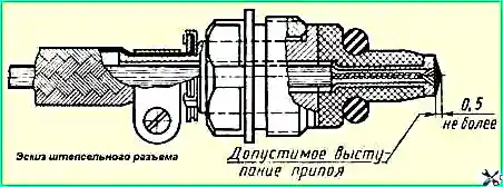
Plug connectors of low voltage outputs are designed for PGVAE 1.5 mm wires 2 (GOST 9751-61) with shielding braid.
When assembling the plug connector, the core of the PGVAE wire must be stripped to a length of 17 mm, assembled with the connector parts so that all the wires of the core fit into the bushing, pull the wire until the wire insulation stops in the contact bushing, separate the ends of the wire and solder them with PIC solder -30 or POS-40 to the contact sleeve without the use of acid and without strong heat to avoid damage to the insulating sleeve and wire insulation.
The soldering must protrude above the end of the contact sleeve by no more than 0.5 mm and must ensure the tightness of the soldered hole of the contact sleeve.
When threading the ends of the screen, do not allow it to be over-tensioned; to secure it, the shielding braided wires must be placed between the connector washers, and the existing ones on Bend one of the tab washers onto the other washer, then secure the screen to the plug connector sleeve with a clamp.
After completing the installation of all wires and the ventilation system, you should check and ensure that all nuts of the low-voltage terminals and ventilation fittings, as well as the bolted connections of the distributor, are tightened until they stop.
When tightening the coupling bolts that secure the screen cover and screen, do not allow them to be overtightened, since the sealing of the joints of the cover with the screen and the screen with the body is structurally reliably ensured by rubber sealing rings when the end metal surfaces come into contact at the sealing points;
Further tightening of the bolts does not improve the tightness, but will only inevitably lead to the thread breaking or the bolt head coming off; Likewise, when wrapping low-voltage contacts of high-voltage terminal connectors, they should not be over-tightened; sealing in the leads and connectors is ensured by rubber sealing rings when the nuts are screwed in until they stop.
When filling plug connectors, you must ensure that the ignition coil leads are connected correctly in accordance with the terminal markings (VK and P).
If installation is carried out with the ignition on, then connect the wires to the VK connector last.
When tightening the nuts of the low-voltage connectors, you should hold the shielding braid by the clamp, preventing it from twisting.
During operation, it is necessary to maintain the breaker contacts in good condition (i.e., monitor their cleanliness and adjustment).
It is necessary to ensure the lubrication of rubbing parts; Excessive lubrication of the distributor is harmful, as it can lead to rapid wear of the breaker contacts when oil gets on them and to failure of the distributor.
It is necessary to ensure the cleanliness of the distributor and its parts, especially the insulating parts (cover, slider, terminals, etc.).
After each, even partial disassembly of the distributor, it is necessary to ensure its tightness by correctly laying the rubber o-rings and tightening the fasteners of the screen-to-body connections, the screen cover to the screen, the nuts of the high-voltage fittings and the low-voltage plug connector to the stop, ensuring the timely replacement of worn out rubber seals rings with new ones (attached to the distributor), as well as tightening the fittings of the ventilation pipes of the air supply and exhaust as far as possible, while not allowing the nuts and bolt connections to be overtightened.
It is necessary to ensure the reliability of the connection of high-voltage wires with the terminals of the distributor cover and coil, as well as the wires with the connector contacts.
It is necessary to ensure the reliability of all connections of the shielding parts on the engine. It is necessary to protect plastic parts from damage (the slider caps and the ember in the distributor cap).
Make sure that fuel and oil from the engine do not enter the distributor.
It is necessary to maintain the tightness of the entire ignition system by ensuring that the union nuts of the high voltage wire hoses, connectors and screen parts are tightened.
The ignition coil must be protected from mechanical damage.
For TO-2 you need:
- 1. Turn the oiler cap one turn to supply lubricant to the distributor shaft.
- 2. Wipe the plastic distributor cap with a clean, dry or gasoline-soaked rag.
- 3. Inspect the cam and, if it is dirty, wipe it with a rag soaked in gasoline.
- 4. Lubricate the axis of the breaker lever with one drop of oil used to lubricate the engine, lubricate the cam bushing with two to three drops of the same lubricant (having first removed the slider and the oil seal underneath), the cam fillet is impregnated with a special lubricant, and no addition is required.
- 5. After lubrication, check that the lever is not stuck on the axle; To do this, you need to press the lever with your fingers and release it. The released lever should quickly return (under the action of a spring) and the contacts should close with a click.
If the contacts do not close or the lever moves slowly, it is necessary to eliminate the jamming in a repair shop and adjust the tension of the breaker spring within 500-650 g by removing the lever and carefully bending the spring in one direction or another.
- 6. Check the cleanliness of the breaker contacts: if necessary, remove dirt and oil from the contacts by wiping the contacts with chamois soaked in clean gasoline, then pull back the lever, let the gasoline evaporate and wipe the contacts with clean, dry chamois.
Instead of suede, you can use any material that does not leave fibers on the contacts, and instead of gasoline, you can use alcohol to wipe the contacts.
- 7. Check the condition of the working surface of the contacts and only if there is a large transfer of metal from one contact to another, and if the formed tubercle on the contact does not make it possible to measure the gap between the contacts mi, clean them up.
You need to clean the contacts with a thin (about 1 mm) abrasive plate or fine glass sandpaper.
It is prohibited to use sandpaper, needle files or other means other than those specified above to clean contacts.
If any interruptions occur in the operation of the engine, under no circumstances should you clean the contacts of the breaker unless it has been previously established that the interruptions are caused by the breaker.
When cleaning contacts, remove the bump on one of them.
You should not clean the contacts until the crater on the other contact is completely eliminated (deepened). After cleaning, rinse the contacts, dry them as indicated above, and adjust the gap between them.
When cleaning the contacts, it is necessary to saw down their planes, maintaining the necessary parallelism so that during operation the contacts touch each other with the entire plane (without a gap between them)
After each removal of the distributor from the vehicle, it is necessary to check the ignition installation.
- 8. Check and in; If necessary, adjust the gap between the contacts. The gap between the contacts should be within 0.3-0.4 mm.
You need to adjust the gap in the following order:
- a) rotate the distributor shaft until the protrusion of the cam presses the lever cushion so that the largest gap is established between the contacts; loosen the screw securing the fixed contact post and turn the eccentric (located at the fork of the post) with a screwdriver so that a 0.4 mm thick probe fits tightly into the gap between the contacts; c) tighten the screw securing the fixed contact post and check the gap again with the feeler gauge; the dipstick must be clean; Before use, it should be wiped with gasoline.
- 9. If necessary (in case of complete wear of the contacts), it is allowed to replace the breaker lever and contact stand, a set of which is included in the spare parts, once during the entire warranty period of the distributor.
When replacing the lever, use the key supplied with the distributor.
10. Check the condition of the rubber sealing rings and replace them if necessary.
During the entire warranty period, it is allowed to replace the sealing rings twice, two sets of which are included with the vehicle.
Installing the high voltage wire into the ignition coil cover socket. Proper installation of the high voltage wire into the ignition coil cover socket is important to ensure the operation of the ignition system.
If the engine operates for a long time with the wire not installed all the way into the coil socket, sparking occurs between the tip of the wire and the high-voltage terminal embedded in the plastic cover.
As a result, the plastic in the socket may burn out, the electrical strength of the plastic may decrease, and even the ignition coil will lose its functionality.
The following is the procedure for checking the installation of the high voltage wire in the ignition coil cover socket:
- 1. Measure the length of the wire from the end of the tip to the end of the union nut of the hose, pressed towards the tip of the wire. This length should be 70-75 mm.
- 2. Inspect the end of the wire with the lug. Clean off any solder deposits on the tip that prevent the tip from being installed in the socket.
- 3. Check the presence of two rubber sealing rings on the wire, insert the wire all the way into the socket of the ignition coil cover, tighten the fitting and the union nut of the shielding hose.
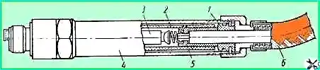
If the length of the wire from the end of the tip to the end of the hose union nut, pressed towards the wire tip, is less than 70 mm, the wire should be reinstalled. for this you need:
1. Remove the distributor screen cover, remove the wire from the central socket of the distributor cover and, unscrewing the fitting and union nut of the hose, pull the wire out of the distributor screen.
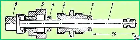
- 2. Move the rubber sealing rings on the wire, carefully pull the wire in the shielding hose towards the output to the ignition coil and install the first rubber ring 2 from the wire tip at a distance of 50 mm.
- 3. Insert wire 1 into the ignition coil socket. The wire must enter the socket all the way: the tip of the wire must snap into the groove of the high-voltage terminal of the coil.
Holding the wire with your hand, insert fitting 3 and tighten. Then move the second o-ring 4 to the fitting, tighten the union nut 5.
- 4. Connect the second end of shielding hose 6 to the high-voltage terminal of the shield distributor and insert the wire into the central socket of the distributor cover until it stops.
- 5. Place the screen cover, tighten the bolts and union nuts of the screen hose.
Caring for spark plugs. When performing maintenance 1 again, the spark plugs must be turned out and their condition checked.
1. Check the gap between the electrodes with a wire feeler gauge. The use of flat feeler gauges is unacceptable, since with a flat feeler gauge the measurement gives an incorrect result (the measured gap is less than the actual one).
If the spark gap is greater than 0.6 mm, it must be adjusted by bending only the side electrode.
When the central electrode is bent, the spark plug insulator skirt is destroyed.
Before adjusting the gap, it is advisable to slightly file the electrodes with a needle file to obtain edges, since in the presence of blunt edges, the voltage required to break through the spark gap increases significantly.
The gap must be adjusted within 0.5-0.6 mm. When operating in winter, it is advisable to set a gap of 0.5 mm.
- 2. If the spark plug insulator is covered with soot and carbon deposits, then the spark plug must be cleaned using a special device for cleaning spark plugs.
- 3. The removable parts of the spark plug (ceramic insulating sleeve of the screen and liner) must be wiped with a clean rag soaked in gasoline.
- 4. If the rubber sealing coupling is severely deformed or has lost elasticity, you should install a new coupling included in the spare parts (the coupling can be replaced once during the warranty period of the spark plug).
- 5. When screwing in and out a spark plug, you must use only a spark plug wrench.
If, when unscrewing the union nut of the hose from the spark plug with a heated engine, the spark plug itself is turned out of the head, then you should not try to hold it by the screen with pliers.
It is better to unscrew the spark plug and then, holding it by the hexagon of the housing with a spark plug wrench, unscrew the nut.
The tightening torque of the hose union nut should be no more than 2.5 kgm, the tightening torque of the spark plug should be no more than 3.5 kgm.
- 6. When installing the spark plug on the engine, it is necessary to check the presence and condition of the sealing ring.
During normal operation of the spark plugs on the engine, the insulator skirt should be brown. The light yellow (almost white) color of the insulator indicates significant overheating of the spark plug.
The thermal characteristics of the spark plug SNZ07 fully correspond to the operating conditions of this plug on the engine in all modes of Normal operation of the latter.
In particular, the spark plug does not create glow ignition during prolonged engine operation in fully open throttle modes.
Often mistaken for glow ignition, the phenomenon of the so-called “coasting” of the engine, i.e., engine operation after the ignition is turned off, usually has nothing to do with abnormal overheating of the spark plugs and is completely eliminated if the heated engine is allowed to run for a short time before turning off the ignition. idling.
A significant “run-out” indicates the presence of a large amount of carbon deposits in the block head.
You should not allow the engine to idle for a long time at a low number of crankshaft revolutions and the car to move for a long time at a low speed in fifth gear, as this will cause the spark plug insulator skirt to become covered with soot and interruptions in the spark plug operation will occur (during subsequent starts of a cold engine ) and the contaminated surface of the insulator is moistened with fuel.
With sooty spark plugs (when the soot is dry on the insulator skirts), starting a cold engine becomes difficult; If the surface of the insulator is moistened with fuel, starting the engine is impossible.
Proper operation of spark plugs largely depends on the thermal state of the engine.
At low air temperatures, the engine must be insulated (use an insulated hood, close the radiator shutters).
After starting a cold engine, you should not immediately move the car, as if the spark plugs are not warmed up enough, interruptions in their operation may occur.
When driving after a long period of parking, long accelerations must be used before changing to higher gears.
Candles may also work intermittently in cases where the rules for starting the engine are not followed or when, while driving, the working mixture is enriched with fuel by closing the carburetor air damper.
")

")
")
")
")
")
")
")