Installing the ignition during engine assembly, as well as on engines from which the distributor and distributor drive have been removed, must be done in the following order:
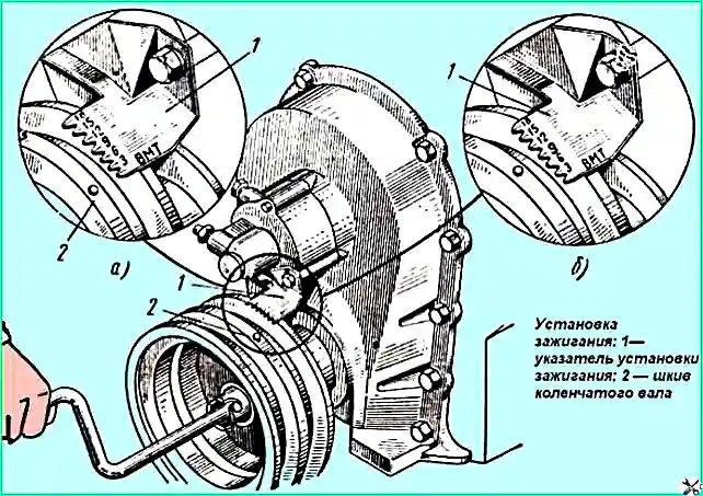
- 1. Set the piston of the first cylinder at the top dead center of the compression stroke by turning the crankshaft until the hole on the crankshaft pulley aligns with the TDC mark on the ignition position indicator located on the maximum speed limiter sensor (Fig. 1, a)
- 2. Position the groove (Fig. 2) on the distributor drive shaft assembly so that the groove is parallel to the mark on the upper flange of the distributor drive housing.
- 3. In this position, it is necessary to insert the distributor drive into the block socket, and before starting this operation, it is necessary to position the holes in the lower flange of the drive housing exactly above the threaded holes for the bolts securing the distributor housing to the block.
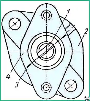
After the distributor drive is in place, the angle between the axis of the groove on the drive shaft and the axis connecting the holes on the upper flange of the distributor body must be within 15°.
If the angle is larger, the drive gear should be adjusted relative to the camshaft gear by one tooth, keeping the angle within the specified limits; in this case, the groove on the drive shaft should be offset towards the front end of the engine.
If in this case the drive housing cannot be seated until the gap between its lower flange and the flange on the block is eliminated (which indicates a mismatch between the tenon on the distributor drive shaft and the groove on the oil pump shaft), it is necessary to turn the engine crankshaft two revolutions while simultaneously light pressure on the distributor drive housing.
- 4. Turn the engine crankshaft to the value of the ignition timing setting angle; to do this, by rotating the engine crankshaft with the starting handle, at the end of the second revolution, align the hole in the crankshaft pulley with mark 9 on the ignition timing indicator (Fig. 1, b).
- 5. Loosen the bolt securing the plate to the distributor and insert the distributor into the distributor drive socket so that the octane corrector is directed upward.
In this case, the rotor electrode will be located against the terminal of the first cylinder on the distributor cap.
Turn on the ignition and turn the distributor body counterclockwise until a spark appears between the end of the central wire coming from the ignition coil and the ground (the gap between the end of the wire and the ground should be 2-3 mm).
- 6. With this position of the distributor body, tighten the bolt securing the plate to the distributor.
Check that the wires in the distributor cap are installed correctly in accordance with the firing order in the cylinders (1—5—4—2—6—3—7—8).
Before installing the ignition, check and, if necessary, adjust the gap between the contacts of the breaker, and also align the index arrow of the upper plate of the octane corrector with the 0 mark on the bottom plate.
Installation of the ignition in engines from which the distributor was removed for adjustment and repair, but the distributor drive was not removed, must be done in accordance with the instructions given in paragraphs. 3—6.
The ignition installation on engines on which neither the distributor nor its drive has been removed is carried out in accordance with the instructions given in paragraphs. 3, 5 and 6, slightly unscrewing the bolt securing the plate to the distributor before the operation specified in paragraph 5.
The ignition setting on the engine in accordance with the type of gasoline used must be clarified using the scale on the top plate of the distributor (octane corrector scale) by road testing the vehicle with a load until detonation occurs as follows:
- 1. Warm up the engine and drive along a flat section of the road in direct gear at a steady speed of 30 km/h.
- 2. Sharply press the throttle pedal all the way and hold it in this position until the speed increases to 60 km/h; in this case, you need to listen to the engine.
- 3. In case of strong detonation in the engine operating mode specified in paragraph 2, by rotating the octane corrector nuts, move the index arrow of the upper plate along scale towards the “─” sign.
- 4. If there is complete absence of detonation in the engine operating mode specified in paragraph 2, by rotating the octane corrector nuts, move the arrow of the upper plate along the scale to the side marked “+”.
If the ignition is installed correctly, when the car accelerates, a slight detonation will be heard, which disappears at a speed of 40-45 km/h.
")

")
")
")
")
")
")
")