Adjusting the kingpin bearings
The kingpin bearings of the front drive axle steering knuckle are adjusted with a preliminary load
The torque required for smooth rotation of the knuckle should be 0.5-0.8 kgm, which corresponds to a force of 2-2.4 kgm applied to the hole in the steering trapezoid lever.
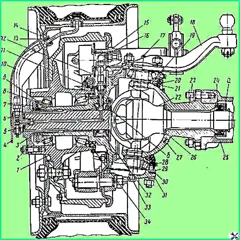
In this case, the bearings should be lubricated with the grease specified in the lubrication chart, axle shaft 22 (see Fig. 1) removed, oil seal 20 of the steering knuckle housing removed, and the fastening nuts of the steering knuckle housing linings tightened to a torque of 16-18 kgm.
Axial movement of the bearings is not allowed.
The absence of axial movement can be checked without removing the front drive axle from the car.
To do this, you need to lift the front axle onto jacks, unscrew the plug 33 in the lower lining 31 of the steering knuckle housing, install an indicator on the lining, resting its leg against the end of the kingpin
And using a jack or lever, try to move the steering knuckle housing upward, the movement of the indicator arrow will indicate the presence of axial movement in the bearings and the need to adjust them.
In order to eliminate axial movement resulting from bearing wear, you need to remove the required number of adjusting linings - 30 from under the lower lining, since the lower bearing is usually more worn.
If, when disassembling the units, it turned out that the wear of the bearings is approximately the same, you need to remove the same number of gaskets from under the upper and lower pads.
If the lower kingpin bearing is heavily worn, it is recommended to swap the bearings; In this case, the shims must be removed from under the upper pad.
When installing new high-precision bearings with part number 27308U (see the stamp on the end face of the bearing ring), after the final adjustment of the preload, sets of adjusting shims of the same thickness must be installed under the upper and lower pads.
The difference in the thickness of the shim sets under the upper and lower pads is allowed to be no more than 0.05 mm.
When installing new normal-precision bearings with part number 27308, it is necessary to first measure their mounting height (the size from the support end face of the outer ring to the support end face of the inner ring).
The thickness of the shim set installed on the side of the bearing with a greater mounting height must be correspondingly greater by the amount of the difference in the mounting heights of the bearings.
Failure to comply with the above Failure to follow the installation rules for adjusting shims results in the loss of alignment of the steering knuckle housing and the ball joint.
After final adjustment of the new bearings, each of the shim sets must include at least ten 0.1 mm thick shims, two 0.05 mm thick shims and one 0.1 mm thick shim must be installed in the shim set on the side of the steering knuckle housing 29, and the remaining thin shims must be installed on the side of the lining 31 (or steering arm 18) to obtain a tight, leak-proof connection.
During adjustment, it is necessary to rotate the steering knuckle housing several times so that the bearing rollers take the correct position between the bearing rings.
Adjusting the wheel hub bearings
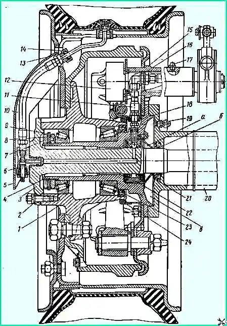
With the tapered roller bearings of hub 1 (see Fig. 2) the wheel should rotate freely by hand, but should not have a noticeable wobble.
Check the bearing adjustment:
- a) for the rear and middle axles - with the half-shaft 3 removed;
- b) for the front drive axle - with the flange 2 (Fig. 1) of the half-shaft joint knuckle closed.
To adjust the wheel hub bearings, tighten the nut 8 (see Fig. 2) of the bearing fastening until the hub starts braking and then loosen it by approximately ¼ turn, until the locking pin of the nut coincides with the nearest hole in the lock washer.
The tightening torque of the lock nut 7 after the adjustment is complete should be 12-15 kgm.