The water pump is centrifugal and is mounted on the front end of the cylinder block
The pump shaft rotates in two ball bearings that have seals that serve to retain grease in the bearings and protect them from contamination.
The place where the rear end of the shaft exits the water pump bearing housing is sealed with a self-tightening oil seal 13.
The oil seal consists of a graphitized textolite sealing washer, a rubber seal, a spring that presses the washer to the end of the bearing housing 9, and two spring cages.
The protrusions of the washer enter the grooves of the impeller hub 12.
A special cage 15 holds the parts of the oil seal in the impeller when mounting the impeller on the water pump shaft pump.
The cavity between the bearings is filled with grease specified in the lubrication chart.
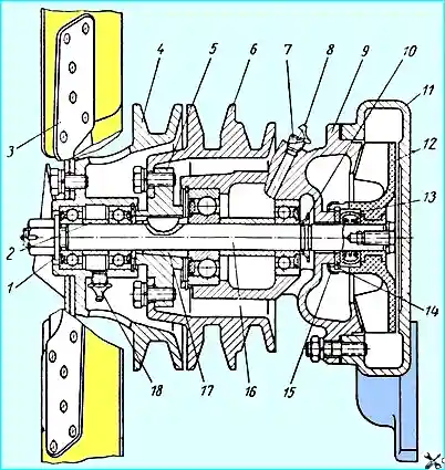
The following are installed at the front end of the shaft: fan pulley 3 on bearings and hub 5 of the water pump pulley.
The hub of the water pump pulley is secured to the shaft using a split conical bushing 17, a key and a nut with a cotter pin.
This fastening allows the pulley hub to be tightened during operation if the pulley fits loose.
It is necessary to periodically check the fastening of the water pump hub, since loosening of the water pump pulley fastening can lead to damage to the fan, radiator and water pump.
To do this, periodically check the tightening of the pulley hub fastening nut.
If the connection loosens, immediately tighten the nut, first removing cotter pin.
The tightening force of the nut should be within 8.5-10 kgm. After tightening, the nut must be carefully cotter-pinned.
Before filling the water pump bearing cavity with grease, unscrew plug 7, which closes the inspection hole.
Filling must be done until fresh grease appears from the inspection hole, then the plug must be put back in place.
The water pump is driven by a V-belt from the engine crankshaft pulley.
The water pump drive belt also drives the power steering pump.
The belt tension is adjusted by moving the power steering pump.
With normal tension, the belt deflection under a force of 4 kg should be within 8-14 mm (Fig. 2).
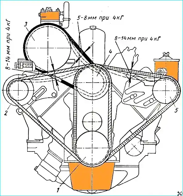
Drive belt tension check diagram: 1 - crankshaft pulley; 2 - alternator pulley; 3 - compressor pulley; 4 - water pump pulley and fan pulley; 5 - power steering pump pulley
Six-blade fan with curved blade ends.
The fan is enclosed in a casing mounted on the radiator frame, which helps increase the speed of air flow sucked through the radiator.
The fan pulley is located on the front end of the water pump shaft on bearings (Fig. 1), which allows you to stop the fan rotation when overcoming deep fords by loosening the drive belt without stopping the rotation of the water pump, compressor and power steering pump.
The fan is driven by a V-belt from the engine crankshaft pulley.
The fan drive belt also drives the generator.
The belt tension is adjusted by turning the generator on the bracket.
The belt tension standard is as follows same as for the water pump belt.
The compressor is driven by the water pump pulley.
With normal tension, the belt deflection under a force of 4 kg should be 5-8 mm.
")

")
")
")
")
")
")
")