The vehicle is equipped with independent brakes — hand and foot
The hand brake is a shoe brake, drum type, with two inner shoes, installed on the transfer case
The hand brake should only be used as a parking brake.
Using the hand brake while driving is only permitted in emergency situations, since it places a heavy load on the power transmission mechanisms, and with prolonged braking of the vehicle, the brake heats up to a high temperature and may fail.
Remember that when braking with the handbrake, the brake signal does not light.
The foot brake drive is pneumatic and acts through the pedal and the pneumatic mechanism system on the shoe-type brakes installed on all six wheels of the car.
The pneumatic system provides the ability to automatically activate the trailer brakes if the trailer is equipped with brakes with a single-line pneumatic drive, and is also used to regulate the air pressure in the tires, activate the windshield wiper and control the transfer case.
Braking is carried out by compressed air pumped into three air cylinders by a compressor driven by a V-belt from the car engine.
Compressed air is supplied from the air cylinders to the brake chambers of the wheel brakes by a brake valve. to control the brake valve there is a pedal connected by a rod to the lever of the valve.
When the pedal is pressed, compressed air from the cylinder enters the brake chambers through the brake valve.
Under the air pressure, the piston rods of the brake chambers move, thereby turning the expanding cams, which press the shoes against the brake drums.
When the pedal is released, the brake valve closes the air supply from the cylinders and releases air from the brake chambers into the atmosphere.
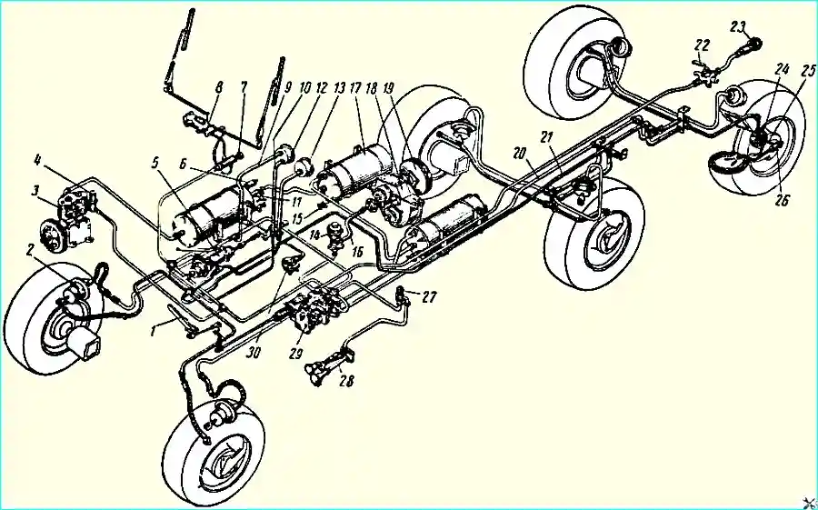
The diagram of the pneumatic brake drive and the air pressure regulation system in the tires are shown in Fig. 1.
Pneumatic wheel brake drive
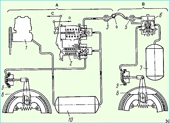
The wheel brake control drive is pneumatic. The force applied by the driver to the pedal is transmitted through a system of levers and rods to the brake valve.
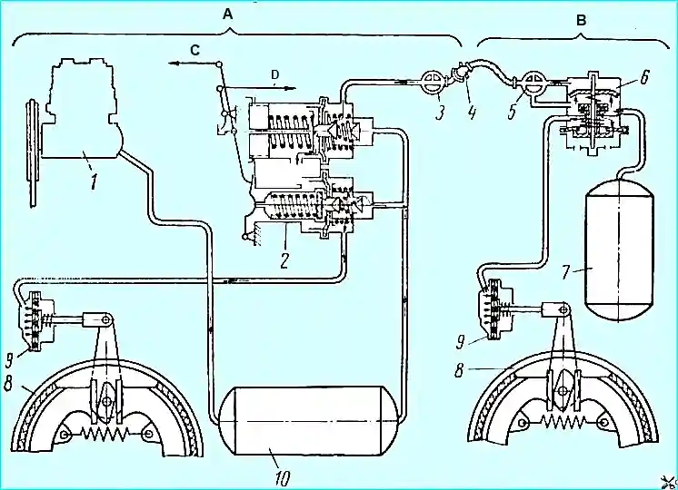
The diagram of the operation of the pneumatic brake drive of a car and trailer is shown in Fig. 1 and 2.
")

")
")
")
")
")
")
")