Axle design of the ZIL-131 car
The rear and middle axles of the car are driving.
Front axle - steered and driven
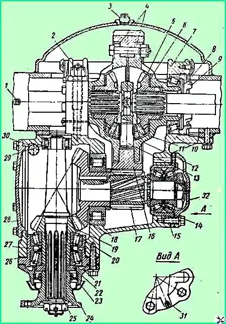
The design of the rear and middle axles is shown in Fig. 1.
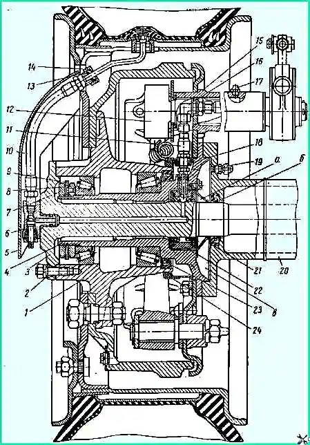
Middle and rear axle hub (front view): 1 - hub; 2 - expansion sleeve; 3 - right axle shaft; 4 - axle; 5 - protective casing of the air supply tube to the wheel tire; 6 - tire tap; 7 - external bearing nut; 8 - inner nut of bearings; 9 - lock washer; 10 - hose supplying air to the tire; 11 - air supply hose to the air supply head; 12 - expansion fist; 13 - oil seal; 14 - nut; 15 - brake bracket; 16 - square; 17 - oiler; 18 - hose tip seal; 19 - breather; 20 - crankcase; 21 - axle shaft seal; 22 - air supply head; 23 - inner hub seal; 24 - outer hub seal
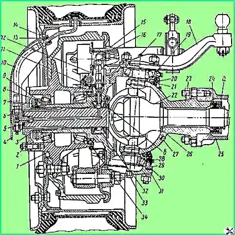
The design of the rear, middle and front axle gearboxes is shown in Fig. 2 and 3.
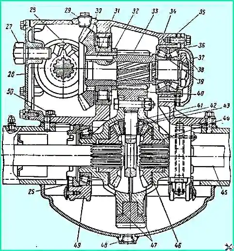
Middle and rear axle gearbox (front view): 25 - differential bearing nut; 26 cover; 27 - bolt puller; 28 - drive bevel gear; 29 - filler plug; 30 - driven bevel gear; 31 - key; 32 - spacer ring; 33 - drive cylindrical gear; 34 - bearing seat; 35 - adjusting shims; 36 - double-row bearing; 37 - bearing cover; 38 - nut of the bearing of the drive cylindrical gear; 39 - adjusting ring; 40 - driven cylindrical gear; 41 - satellite support washer; 42 - satellite; 43 - differential cross; 44 - axle gear; 45 - axle shaft; 46 - axle gear support washer; 47 - differential cups; 48 - drain plug; 49 - gear housing; 50 - gearbox housing mounting bolt
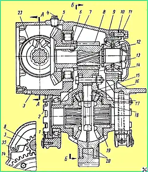
The design of the steering knuckle and the front axle wheel drive is shown in Fig. 4.
The main axle gears are double, consisting of a pair of bevel gears with spiral teeth and a pair of cylindrical gears with oblique teeth.
The gear ratio of the bevel pair is 1.727, the gear ratio of the cylindrical pair is 4.25 and the total gear ratio is 7.339.
The gearboxes (Fig. 2) of the rear and middle axles are installed on top of the axle housing and are attached to it with a horizontal flange.
The gearboxes of the rear and middle axles have the following differences.
At both ends of the drive bevel gear shaft of the middle axle reducer, flanges 29 and 33 are installed for fastening cardan shafts. A larger flange 33 is installed at the front end of the shaft, and a smaller flange 29 is installed at the rear end of the shaft.
The tapered roller bearing 31 is closed by a cover 28 with an oil seal installed in it.
The thrust washer 30 of the inner ring of the roller bearing is equipped with an oil removal groove with a right-hand spiral direction and is marked “C” on the end.
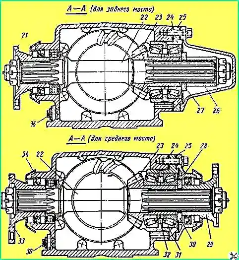
Middle and rear axle gearbox: 21, 29, 33 - flanges for fastening cardan shafts; 22 - through shaft; 23 - drive bevel gear; 24 - adjusting shims; 25 - cup of bearings; 26 - spacer sleeve; 27 - washer; 28 - bearing cover; 30 oil removal washer; 31 - tapered roller bearing; 32 - for bearing lubrication; 34 - oil seal; 35 - oil channel; 36 - drain plug
At the front end of the drive bevel gear shaft of the rear axle gearbox, a flange 21 is installed, having the same dimensions as the flange 29 of the rear end of the middle axle gearbox shaft.
At the rear end of the rear axle gearbox shaft, a spacer sleeve 26 is installed instead of a flange, and the tapered roller bearing and the end of the shaft are closed with a blank cover.
Middle and rear axle gearbox with differential: 1 - nut stopper; 2 - differential bearing nut; 3 - gear housing; 4 - filler plug; 5 - driven bevel gear; 6 - key; 7 - spacer ring; 8 - drive cylindrical gear; 9 - bearing seat; 10 - adjusting shims; 11 - cover ring; 12 - double-row roller bearing; 13 - adjusting ring. 14 - driven cylindrical gear; 15 - support shaft 6a; 16 - satellite; 17 - differential cross; 18 - gear poluosi; 19 - axle gear support washer; 20 - differential cup
The thrust washer 27 does not have an oil removal groove. Otherwise, the details of the rear and middle axle gearboxes are the same.
The gearbox (Fig. 3) of the front axle is attached to the axle housing with a vertical flange.
Gears, differentials, bearing housings, flange 24 of the drive bevel gear shaft and all bearings, except bearing 29 of the front end of the drive bevel gear shaft of the front axle gearbox, are the same as the parts of the rear axle gearbox.
Thrust washer 22 of the inner ring of the tapered roller bearing of the drive bevel gear has an oil removal groove with a left-hand spiral direction and a “P” stamp on the end.
Front axle gearbox with differential: 1 - breather; 2 - nut securing the differential bearing cover; 3 - control hole plug; 4 - differential cups; 5 - axle gear; 6 - support washer; 7 - bearing cover; 8 - nut stopper; 9 - adjusting nut; 10 - gearbox housing; 11 - satellite; 12 - satellite support washer; 13 - differential crosspiece; 14 - bearing seat; 15 - adjusting shims; 16 - driven cylindrical gear; 17 - drive cylindrical gear; 17 - driven bevel gear; 19 - drive bevel gear; 20 - cup of bearings; 21 - bearing cover; 22 - oil washer; 23 - oil seal; 24 - flange; 25 - drive bevel gear shaft; 26 - adjusting shims; 27 - adjusting washers; 28 - cover; 29 - cylindrical roller bearing; 30 - drain plug; 31 - blind plug; 32 - cover
In cover 26 (see Fig. 1) of the right hatch of the gearbox housing of the rear and middle axles, a bolt puller 27 is installed, which serves to press out the reaction rod pin from the upper reaction arm of the rear suspension.
In the flange of the cover 32 (Fig. 3) of the double-row tapered roller bearing of the drive cylindrical gear of the front axle gearbox there is a threaded hole in which a plug 31 is screwed in for storage, used to close the hole in the clutch housing when fording.
Drive to the drive wheels of the front axle: 1 - hub; 2 - flange; 3 - axle; 4 - protective casing of the air supply tube; 5 - channel for air supply; 6 - tire tap; 7 - external nut; 8 - internal nut; 9 - lock washer; 10 - air supply hose to the tire; 11 - external oil seal; 12- air supply hose to the air supply head. 13 - oil seal; 14 - nut; 15 - brake bracket; 10 - square; 17 - oiler; 18 - rotary lever; 19 - adjusting shims; 20 - steering knuckle housing oil seal; 21 - oil seal; 22 - axle shaft assembled with a fist; 23 - ball joint; 24 - axle shaft seal; 25 - crankcase; 26 - support washer; 27 - control hole plug; 28 - plug; 29 - steering knuckle housing; 30 - lower adjusting shims; 31 - lower lining of the steering knuckle; 32 - air supply head; 33 - plug; 34 - inner hub seal
The front drive axle is equipped with steering knuckles and a steering linkage.
At the base of the steering linkage arms, thrust bolts are screwed into the steering knuckle housings and welded, limiting the angles of rotation of the wheels.
Half shafts 22 (Fig. 4) of the front drive axle are equipped with ball joints of constant angular velocity.
On the journals of the axle shafts of the rear and middle axles, as well as on the journals of the cam joints of the axle shafts of the front drive axle, heads 32 (Fig. 4) and 22 (see Fig. 1) are installed for supplying air to the wheel tires.
On the outer ends of the axle flanges, tire valves 6 are installed (see Fig. 1 and 4).
In the upper walls of the gearbox housings of all axles there are filling holes closed with plugs.
Through these holes you can check the condition of the bevel gear teeth and the correct contact pattern.
")

")
")
")
")
")
")
")