Prolonged operation of the engine with incorrect clearances can lead to premature wear of valve mechanism parts - burning of valves, wear of rocker arms, bearing surfaces of pushers and camshaft cams.
If knocking occurs in the valve mechanism, it is necessary to check and, if necessary, adjust the gaps between the valves and rocker arms, which should be within 0.25-0.3 mm (for intake and exhaust valves).
Adjustment of clearances in the valve mechanism is carried out on a cold engine using an adjusting screw with a lock nut installed in the short arm of the rocker.
To adjust the clearance in the valve mechanism, you need to set the piston of the first cylinder to the top dead center (TDC) of the compression stroke.
In this case, the hole on the crankshaft pulley should be located under the “TDC” mark on the ignition timing indicator located on the maximum speed limiter sensor.
In this position it is necessary to adjust the clearance of the following valves;
- - inlet and outlet first cylinder
- - exhaust second cylinder
- - inlet third
- - fourth graduation
- - fifth graduation
- - inlet seventh
- - intake eighth
The clearances of the remaining valves must be adjusted after turning the crankshaft 360° (full revolution).
Adjustment in the second method is carried out in the following order:
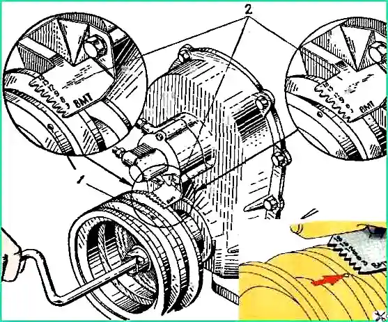
Install the piston of the first cylinder to TDC of the compression stroke using an installation gear indicator (Fig. 1)
To do this, turn the crankshaft until the mark on the shaft pulley aligns with the TDC mark on the indicator.
In this case, both valves, inlet and outlet, of the first cylinder will be closed, and the largest gap will form between the valve stem and the pressure end of the rocker arm, which we measure with a feeler gauge and, if necessary, adjust.
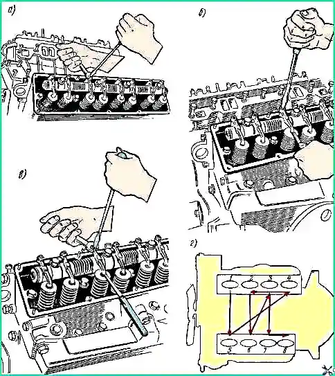
To adjust the gap, hold the adjusting screw with a screwdriver, loosen the lock nut with a wrench, then insert a feeler gauge between the valve stem and the pressure end of the rocker arm and turn the adjusting screw with a screwdriver, setting the required gap.
Then, leaving the dipstick in the gap, we secure the adjusting screw with a locknut using a wrench and a screwdriver.
After adjustment, the gap should be 0.25-0.30 mm for the intake and exhaust valves, while the 0.25 mm feeler gauge should pass freely through the gap, and the 0.30 mm feeler gauge should not pass through.
To adjust the valve clearance of the remaining seven cylinders, turn the crankshaft with the handle one quarter turn (90°) and carry out the adjustment according to the specified method.
The adjustments are carried out sequentially, according to the order of operation of the cylinders 1-5-4-2-6-3-7-8, which is depicted by dotted lines with arrows.
To accurately turn the crankshaft one quarter turn, we make chalk marks on the crankshaft pulley, placing them at an angle of 90° when the piston of the first cylinder is at TDC (compression stroke).
")

")
")
")
")
")
")
")