The tapered roller bearings of the drive bevel gear shaft of the gearbox are adjusted with a slight preload; axial clearance is not allowed
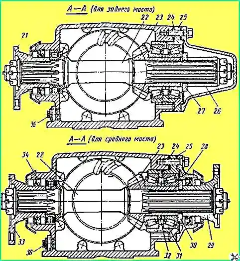
The torque required to turn the shaft in the bearings must be within 0.08-0.16 kgm, which corresponds to a force of 1.3-2.7 kgf applied to the hole in flange 21 (for the middle axle reducer - to the hole in the smaller flange 29).
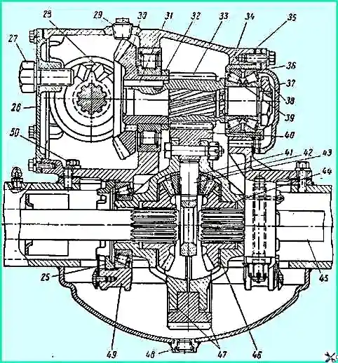
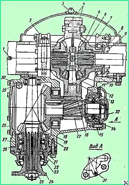
Middle and rear axle gearbox with differential: 1 - nut lock; 2 - differential bearing nut; 3 - gearbox housing; 4 - filler plug; 5 - driven bevel gear; 6 - key; 7 - spacer ring; 8 - leading cylindrical gear; 9 - bearing seat; 10 - adjusting shims; 11 - cover ring; 12 - double-row roller bearing; 13 - adjusting ring. 14 - driven cylindrical gear; 15 - support washer; 16 - satellite; 17 - differential crosspiece; 18 - half-shaft gear; 19 - support washer of half-shaft gear; 20 - differential cup
The torque can be checked using a spring balance (dynamometer).
The torque must be measured by smoothly turning the flange in one direction and after at least five full shaft revolutions.
The bearings must be lubricated with the grease specified in the lubrication chart.
When checking the torque of the drive gear of the front and middle axles, the bearing cover 28 must be moved so that the centering protrusion of the bearing cup 25 comes out of the cover seat and the seal does not resist the rotation of the gear, and the drive gear flange fastening nut must be tightened.
The tightening torque of the nut must be 20-25 kgm.
When tightening the nut, it is necessary to turn the drive gear shaft so that the bearing rollers take the correct position between the conical surfaces of the rings.
The bearings of the drive gear should be adjusted by selecting adjusting washers 32 of the required thickness, installed in the amount of 2 pieces between the ends of the inner bearing rings.
The plant produces adjusting washers of the following thicknesses: 7.25; 7.30; 7.40; 7.50; 7.60; 7.70; 7.80 and 7.85 mm.
After final adjustment of the bearings, the drive gear flange fastening nut must be tightened and cotter-pinned.
The double-row tapered roller bearing 12 of the drive cylindrical gear shaft 8 is supplied by the manufacturer with a selected adjusting ring 13 and does not require additional adjustment; the parts of this bearing are not interchangeable, so rearranging the parts from one bearing to another and rearranging the inner bearing rings of one in place of another is unacceptable.
The inner ring of bearing 12, which has a stamp on the end face — the letter V, must be installed on the side of the stamped end face of the outer ring.
After tightening the bearing fastening nut 12, it must be locked by pressing its thin edge into one of the grooves shaft.
The tightening torque should be 35-40 kgm. If it is necessary to unscrew the nut during repair, it should first be unlocked by bending back the thin edge of the nut, pressed into the groove of the threaded end of the shaft.
The leading 23 and driven 5 bevel gears of the gearbox are selected at the factory in sets by the contact patch and lateral clearance in the engagement, lapped and branded with the serial number of the set.
In addition, during the operation of the car, the gears are run in to each other, so if it is necessary to replace the gear, both gears should be replaced at the same time.
Newly installed bevel gears must have one serial number of the set.
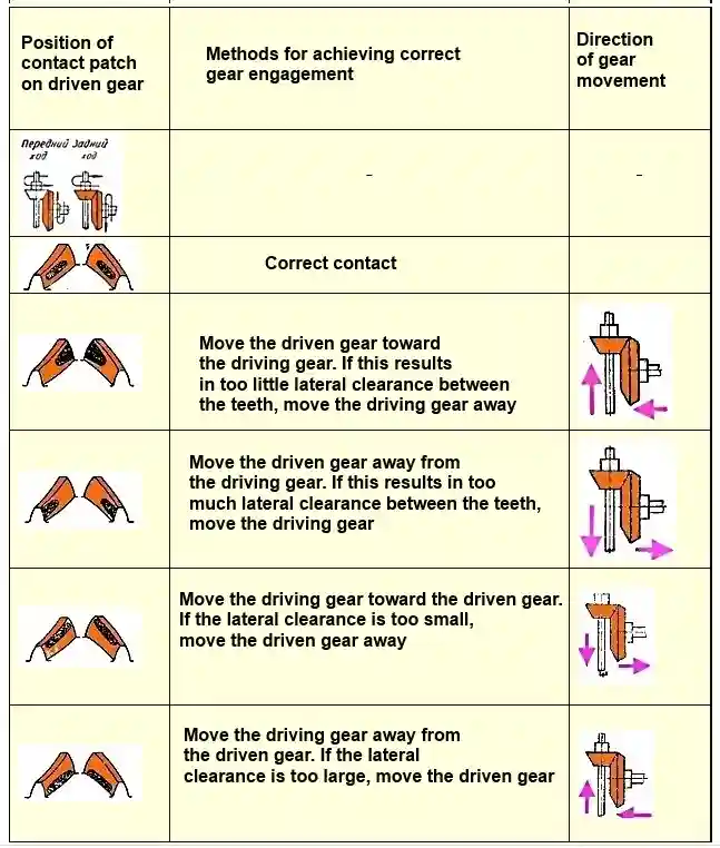
When installing new bevel gears of the gearbox, they must be adjusted by the contact patch, "on the paint" and by the lateral clearance in the engagement (Table 1 at the end of the article)
Contact patch on both sides of the tooth The length of the driven bevel gear should be approximately ⅔ of the tooth length and should not reach the end of the narrow end of the tooth by 2-4 mm, and should not extend to the upper edge of the tooth.
On the driving gear, the contact patch may reach the upper edge of the tooth.
The contact patch is obtained by rotating the driving gear in both directions while braking the driven gear by hand.
The lateral clearance should be within 0.15-0.40 mm at the wide part of the tooth, which corresponds to a rotation of flange 21 of the shaft of the driving bevel gear by 0.18-0.48 mm when measured at the radius of the location of the holes for the bolts and with the driven gear stationary; for the gearbox of the middle bridge, the measurement is made on the smaller flange 29.
The lateral clearance must be checked for at least four teeth of the driven gears located at approximately equal distances around the circumference.
When installing new gears in the gearbox, it is necessary to install adjusting shims 24 with a total thickness of 2 mm under the flange of the cup 25 of the bearings of the driving gear; then adjust the side clearance by moving the driven bevel gear by changing the number of shims 10 under the flange of the seat 9 of the bearings of the driven bevel gear, and check the contact patch.
If the correct contact patch is not obtained, it is necessary to move the bevel gears as indicated in Table. 1, changing the number of shims under the flanges of the bearing cup of the driving gear and the bearing seat of the driven gear.
After the final adjustment, at least two 0.1 mm thick shims must be installed in each set of shims.
Thin shims must be located on both sides of the shim set to obtain a tight, leak-proof connection.
The bolts securing the bearing cup, seat and caps must be tightened after the final adjustment; tightening torque 6-8 kgm.
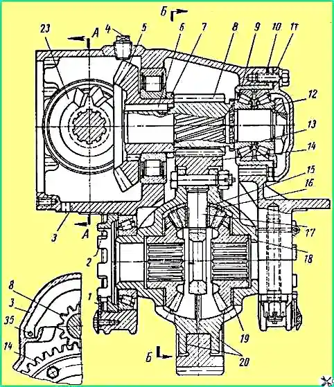
After installing shaft 25 (Fig. 4) together with the bearing cup into the front drive axle gearbox housing, it is necessary to release the bearing rollers from the pressure of the ends against the bearing rings by lightly striking them through a mandrel on the end face of the outer ring of the cylindrical roller bearing 29 from the inside.
The cover 28 of the gearbox housing must be removed.
If the gears have an increased circumferential clearance in the engagement due to wear of the teeth, then they should not be adjusted, since this disrupts the correct engagement.
Bevel gears should operate until completely worn out without additional adjustment.
If the increase in circumferential clearance appeared as a result of wear of the tapered roller bearings, i.e. if simultaneously with the increase in lateral clearance there is a noticeable axial clearance in the bearings, it is possible to reduce side clearance by removing the appropriate number of shims to compensate for this wear; in this case, it is necessary to first restore the preload of the bearings of the leading bevel gear.
After adjustment, it is necessary to check the correctness of the contact patch.
The assembled differential should be installed in the gearbox housing after installation and adjustment of the bevel gears and final Tightening the bearing cap mounting bolts.
After installing the differential assembly with bearings in the gearbox housing socket, tighten the adjusting nuts 2 (see Fig. 3) of the bearings by hand so that they fit tightly against the bearing rings, and then install the differential bearing caps.
If the caps do not fit into place, this means that the adjusting nuts are skewed and need to be tightened again.
Forcibly installing the caps can damage the housing, caps and nuts.
After installing the bearing caps, tighten the cap mounting nuts until they stop and then loosen them enough to turn the adjusting nuts 2.
When tightening and unscrewing the adjusting nuts, it is necessary to shift the differential so that the driven cylindrical gear 14 occupies position symmetrical with respect to drive gear 8.
The tapered roller bearings of the differential must be adjusted with a slight preload.
To do this, first adjust the adjusting nuts so that the differential has an axial movement not exceeding 0.1 mm.
The value of the axial movement must be checked with an indicator installed opposite the crown of the driven cylindrical gear and secured to the bearing cover.
After this, each of the adjusting nuts must be tightened by one groove, locked in this position with stopper 1, tighten the nuts securing the bearing covers and cotter them (the tightening torque should be 17-19 kgm).
When adjusting the bearings, it is necessary to turn the differential several times so that the bearing rollers take the correct position between the conical surfaces rings.
When assembling the differential, it is necessary to ensure that the marks on the cups 20 are installed opposite each other, the tightening torque of the differential bolt nut should be 12-14 kgm.
Adjustment of the bearings and gears of the front drive axle reducer is similar to adjustment of the gearboxes of the rear and middle axles.
It is necessary to remember that when the car is moving forward, the working side of the tooth of the driven bevel gear is the convex side for the rear and middle axles, and the concave side of the tooth for the front axle.