The steel camshaft with hardened cams and distributor drive gear is driven by two gears
The camshaft rests on five supports equipped with bimetallic tape bushings, the diametrical clearances in the camshaft bearings in the new engine are within 0.03-0.09 mm for four front bearings and within 0.025-0.077 mm for the fifth rear bearing.
The axial movement of the camshaft is limited by a flange located between the gear and the front end of the first journal, which is attached to the front end of the block with two bolts.
The difference between the height of the spacer ring put on the front journal of the camshaft and the thickness of the flange is 0.08-0.208 mm.
These values correspond to the axial clearance of the camshaft of a new engine.
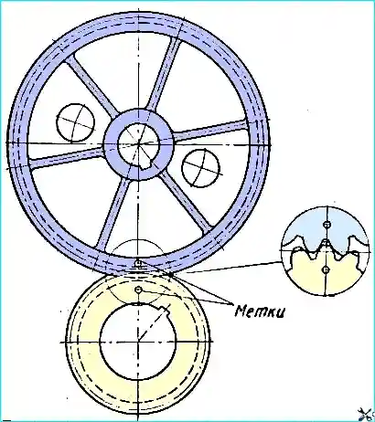
For correct mutual installation of gears, it is necessary to place the crankshaft gear and the camshaft gear so that the marks are on the same line connecting the centers of these gears (Fig. 1).
Valves - upper, located in the cylinder head in one row, inclined to the cylinder axis; are driven by the camshaft using rods, pushers and rocker arms.
The valves are made of heat-resistant steel; - the angle of the working chamfer of the inlet valve seat is 30°, the outlet 45°; the stem of the outlet valve has a drilling filled with sodium, and the plate has a heat-resistant surfacing of the seat chamfer.
To increase their service life, the outlet valves are forcibly rotated during engine operation by a special mechanism.
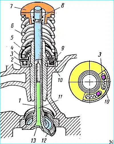
The mechanism of rotation of the exhaust valve (Fig. 2) consists of a fixed housing 2, five balls 3 and their return springs 10 (placed in inclined recesses of the housing, made along an arc), a disk spring 9, a thrust washer 4, on which the valve spring presses through the locking ring 5.
The thrust washer 4 and the disk spring with a gap are put on the projection of the housing, which is located in a special socket of the cylinder head (Fig. 3).
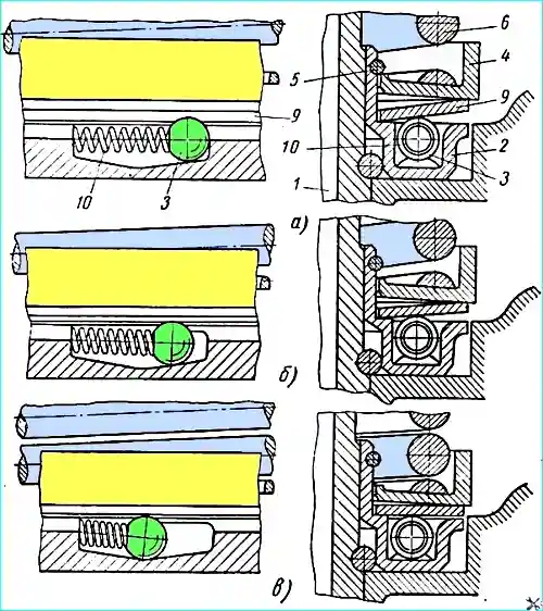
When the valve is closed (Fig. 3, a), the force of spring 6 is transmitted through thrust washer 4 to the outer edge of disk spring 9, whose inner edge rests on the shoulder of housing 2.
When the valve is opened (Fig. 3, b), the force of the valve spring increases; under the action of the increased force, the disk spring, resting on the balls, straightens out;
- a gap appears between the inner edge of the spring and the shoulder of the housing, and the force of the springs 10 begins to be transmitted to the balls 3, which, rolling along the inclined surfaces of the recesses, turn the disk spring 9 and the thrust washer 4 at a certain angle, and with them the valve spring 6 and valve 1.
During valve closing (Fig. 3, c), the force of the valve spring decreases, the deflection of the disk spring increases; it rests against the shoulder of the housing, releasing the balls, which, under the action of the springs, return to their original position, wedging between the washer and the inclined surface of the housing.
Whenever disassembling an engine that has traveled more than 70,000 km, it is necessary to check the condition of the springs 10 (see Fig. 2 and 3) and the balls of the exhaust valve rotation mechanism.
If traces of wear are found on the spring coils, the spring must be turned with the worn section down.
When assembling the valve rotation mechanism, it is necessary to pay attention to the correct installation of the balls and springs.
When correctly assembled, the springs should be spaced placed behind the balls relative to the selected direction of rotation.
Valve rocker arms are forged, steel, with a bronze bushing.
Valve tappets are steel, hollow. to increase the reliability of the cam-tappet pair, a special cast iron is welded onto the end of the tappet.
The lower part of the tappet has holes for draining the oil that gets into the tappet.
The rods are steel, with hardened spherical ends.
The intake gas line made of aluminum alloy, common to both rows of cylinders, is located between the cylinder heads and is equipped with a water jacket for heating the mixture.
The nuts securing the intake gas line to the cylinder head must be tightened evenly, maintaining a crosswise tightening from the middle to the edges of the gas line, so that the rubber gasket is not squeezed out of the joint between the intake pipe and the head.
The tightening torque of the nuts should be within 2-2.5 kgm.
The exhaust gas lines are composite, made of malleable cast iron, one on each side of the block.
The assembly of the composite gas pipeline on the engine must be carried out in the following order:
- - the joint of the gasket must be located under the clamping bolt; the axis of the bolt tightening the clamp on the short arm of the gas pipeline must be perpendicular to the flanges of the gas pipeline fastening to the cylinder head;
- - the axis of the bolt tightening the clamp on the long arm of the gas pipeline must be parallel to the flanges of the gas pipeline fastening to the cylinder head.
The bolt is installed with the head up; tightening torque of bolts 1.4-1.7 kgm.
Tighten the nuts fastening the composite exhaust gas pipeline to the cylinder head in the following sequence: middle flange - first fasten the lower nut, then the upper one, tightening torque 4-4.5 kgm; outer flanges - fasten nuts with a tightening torque of 3-3.5 kgm.